Welcome to STM32-BoardCar repository
2. Basic use of ultrasonic steering gear gimbal
Basic use of ultrasonic steering gear gimbal
Basic use of ultrasonic steering gear gimbal1. Software-Hardware2. Brief principle1. Hardware schematic diagram2、Physical connection diagram3、Control principle3. Project configuration1. Description2. Pin configuration4. Main functions1. User function5. Experimental phenomena
This tutorial demonstrates: How to externally connect and use the ultrasonic servo gimbal on the expansion board and then print the ultrasonic ranging data through the serial port.
1. Software-Hardware
STM32F103CubeIDE
STM32 expansion board
Ultrasonic steering gear head
Type-C data cable or ST-Link
Download programs or simulate the development board·
Serial Assistant
Receive serial port data and print
2. Brief principle
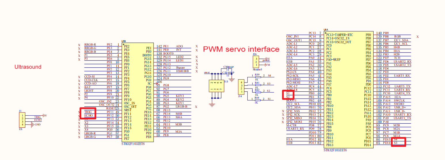
1. Hardware schematic diagram
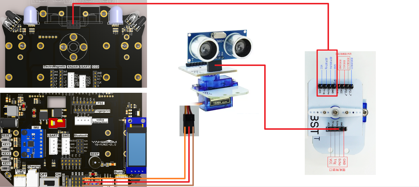
2、Physical connection diagram
3、Control principle
| (Schematic name) | Control pin | Specific meaning |
|---|---|---|
| TRIG | PF11 | Trigger terminal |
| ECHO | PF12 | Receiver |
| S1 | PB0 | Servo control pin |
Ultrasonic Module:
It is a module that uses ultrasonic waves for non-contact physical quantity measurement. It can accurately measure distance, speed, flow and other physical quantities by transmitting and receiving ultrasonic signals, and converts the measurement results into digital signal output. This article will popularize the ultrasonic module Its working principle and function.
Ultrasonic module information for this experiment:
| Model | HC-SR04 | Detection distance | 2-400cm |
|---|---|---|---|
| Working voltage | 5V | High precision | Up to 0.3cm |
| Operating current | 15mA | Dead zone | 2cm |
| Operating frequency | 40KHz | Pin sequence | VCC, Trig (control end), Echo (receiving end), GND |
| Quiescent operating current | <2mA | Input trigger signal | 10uS TTL pulse |
| Sensing angle | Not greater than 15° | Input echo signal | Output TTL level signal, proportional to range |
| Range range | 2cm-4m (peak) | Level output | TTL level |
Ranging principle: Input a high potential for more than 10 microseconds at the trigger end of the ultrasonic module to emit ultrasonic waves. After transmitting the ultrasonic waves and before receiving the returned ultrasonic waves, the receiving end is at a high potential. Therefore, the program can calculate the distance of the measured object from the high pulse duration of the "response" pin.
Test distance = (high level time * speed of sound (340M/S))/2;
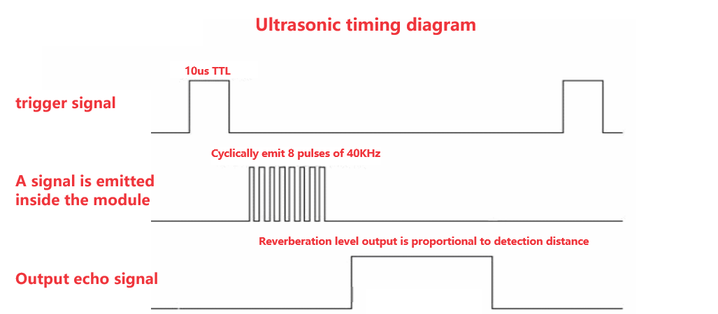
Note: The above timing diagram shows that you only need to provide a pulse trigger signal of more than 10us, and the module will internally send out 8 40kHz cycle levels and detect echoes. Once an echo signal is detected, an echo signal is output. The pulse width of the reverberated signal is proportional to the measured distance. The distance can be calculated from the time interval between the transmitted signal and the received echo signal.
PWM control steering gear principle
The PWM signal is generated by using the timer/counter (TIM) peripheral, and the angle of the servo is controlled by adjusting the duty cycle.
3. Project configuration
1. Description
Omitted project configuration part: New project, chip selection, project configuration, SYS of pin configuration, RCC configuration, clock configuration and project configuration content
Please refer to [2. Development environment construction and use: STM32CubeIDE installation and use] to understand how to configure the omitted parts of the project.
2. Pin configuration
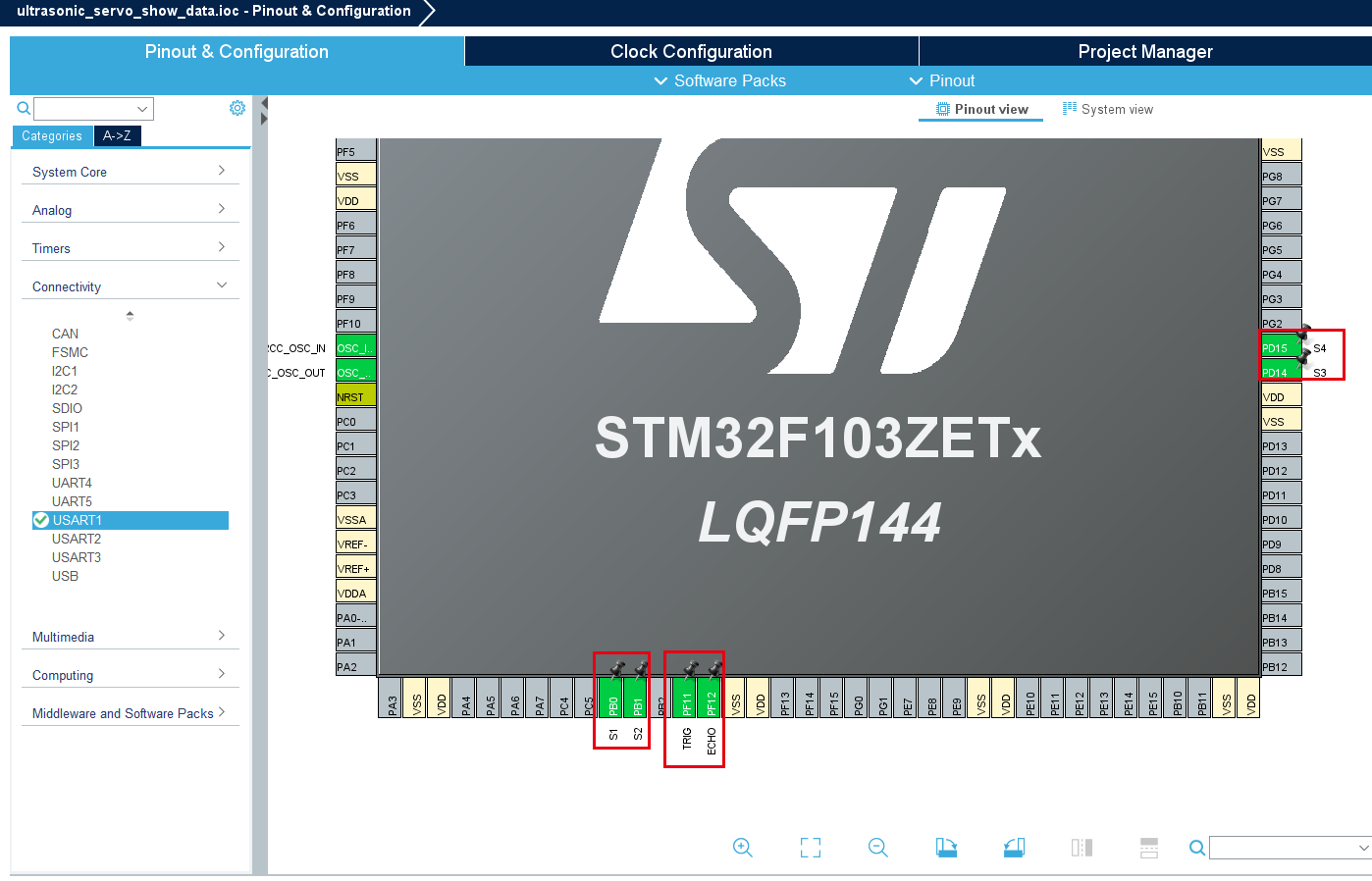
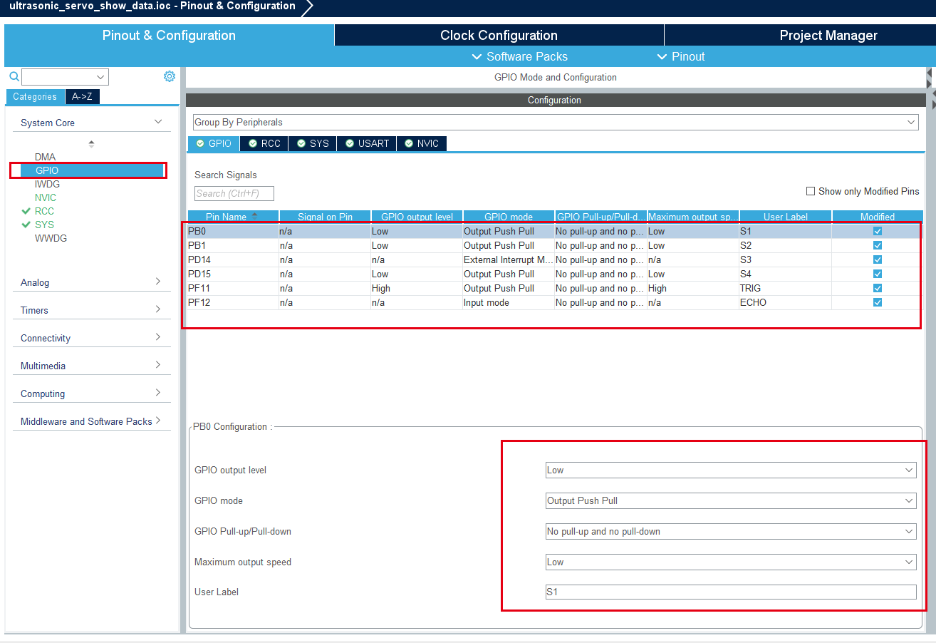
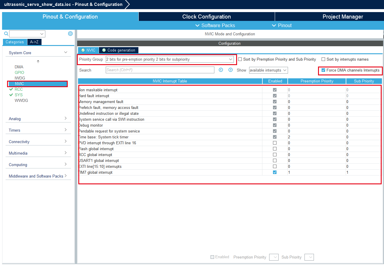
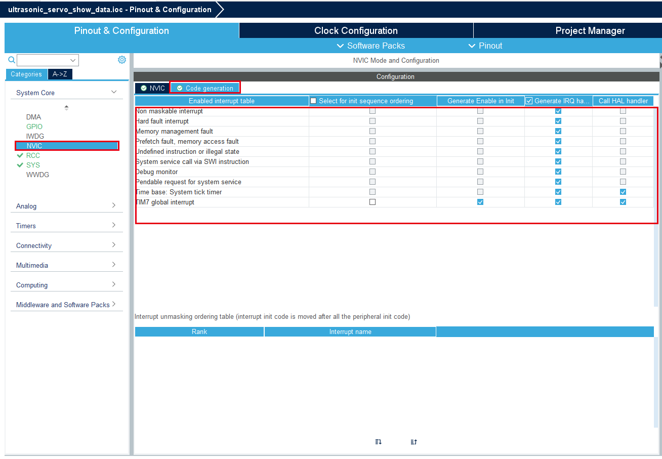
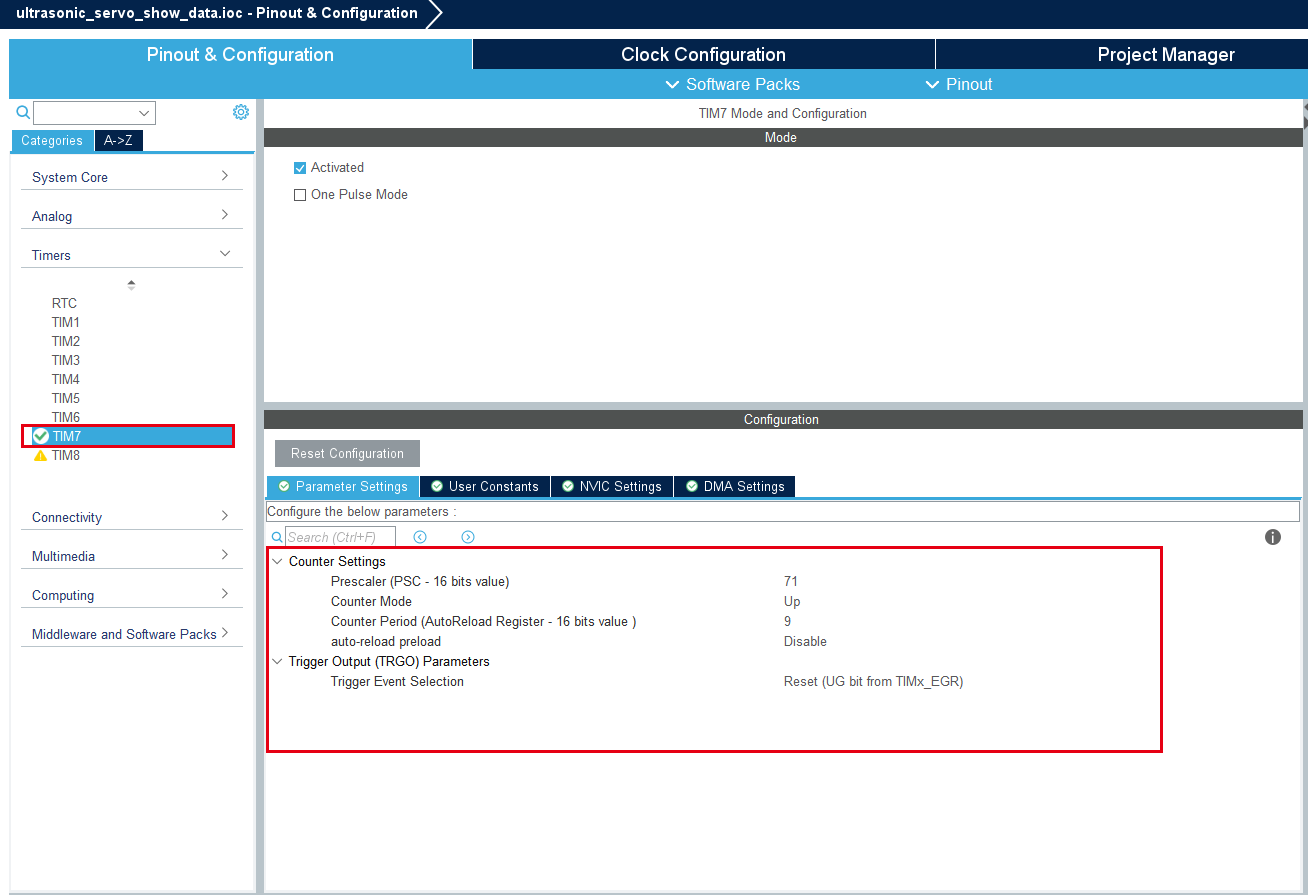
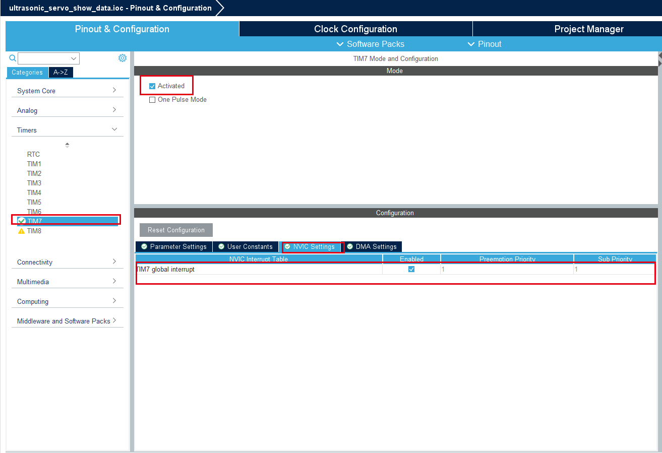
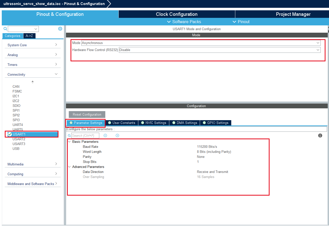
4. Main functions
According to our tutorial STM32CubeIDE can generate the corresponding gpio.c, gpio.h, tim.c and tim.h files. For later transplantation and peripheral module driver, we will place the automatically generated code in the BSP under the project file. folder.
1. User function
Function: Get_distance
| Function prototype | float Get_distance(void) |
|---|---|
| Function description | Get the average of 5 ultrasonic measurement data |
| Input parameters | None |
| Return value | Processed distance |
Function: PwmServo_Set_Angle
| Function prototype | void PwmServo_Set_Angle(uint8_t index, uint8_t angle) |
|---|---|
| Function description | Ultrasonic range detection |
| Input parameter 1 | Servo serial number: 0~MAX_PWM_SERVO-1 |
| Input parameter 2 | Angle value: 0-180 |
| Return value | None |
Function: Bsp_TIM7_Init
| Function prototype | void Bsp_TIM7_Init(void) |
|---|---|
| Function description | Open timer terminal |
| Input parameters | None |
| Return value | None |
Function: Bsp_UART1_Init
| Function prototype | void Bsp_UART1_Init(void) |
|---|---|
| Function description | Initialize serial port 1 |
| Input parameters | None |
| Return value | None |
5. Experimental phenomena
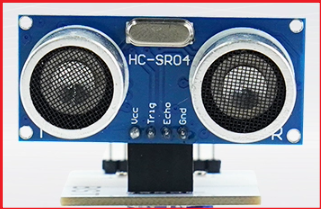
During installation, you need to center the servo before installing it; the [ultrasonic_servo_calibrating.hex] file is provided in the tutorial folder for calibration. After burning this program, the servo will rotate to 90°. At this time, the ultrasonic and servo clouds are installed. Connect the connecting plate of the platform (the actual picture is shown below) to the servo. When installing the ultrasonic wave, it needs to face the front (it will have no effect if it is slightly off).
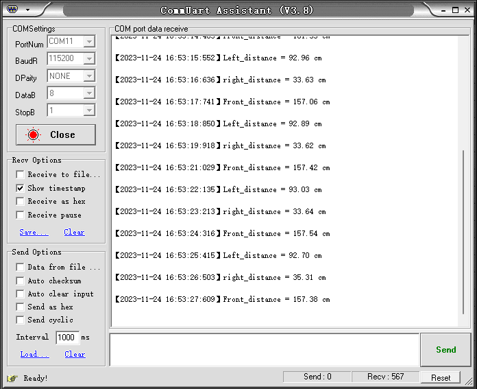
After the servo is calibrated, we can burn the code in this chapter. Then after powering up the car, press the Reset button. We need to connect to the host computer through the type C interface, open the serial port assistant, and set the parameters as shown in the figure below. Then we can view the measured ultrasonic distance through the serial port assistant.
After the car is powered on, the gimbal will first turn to the middle, then to the left, and then to the right. Cycle back and forth in these three directions. The serial port will print the distance between the ultrasonic measurement and the obstacle.
xxxxxxxxxxFor program download, please refer to [2. Development environment construction and use: program download and simulation]
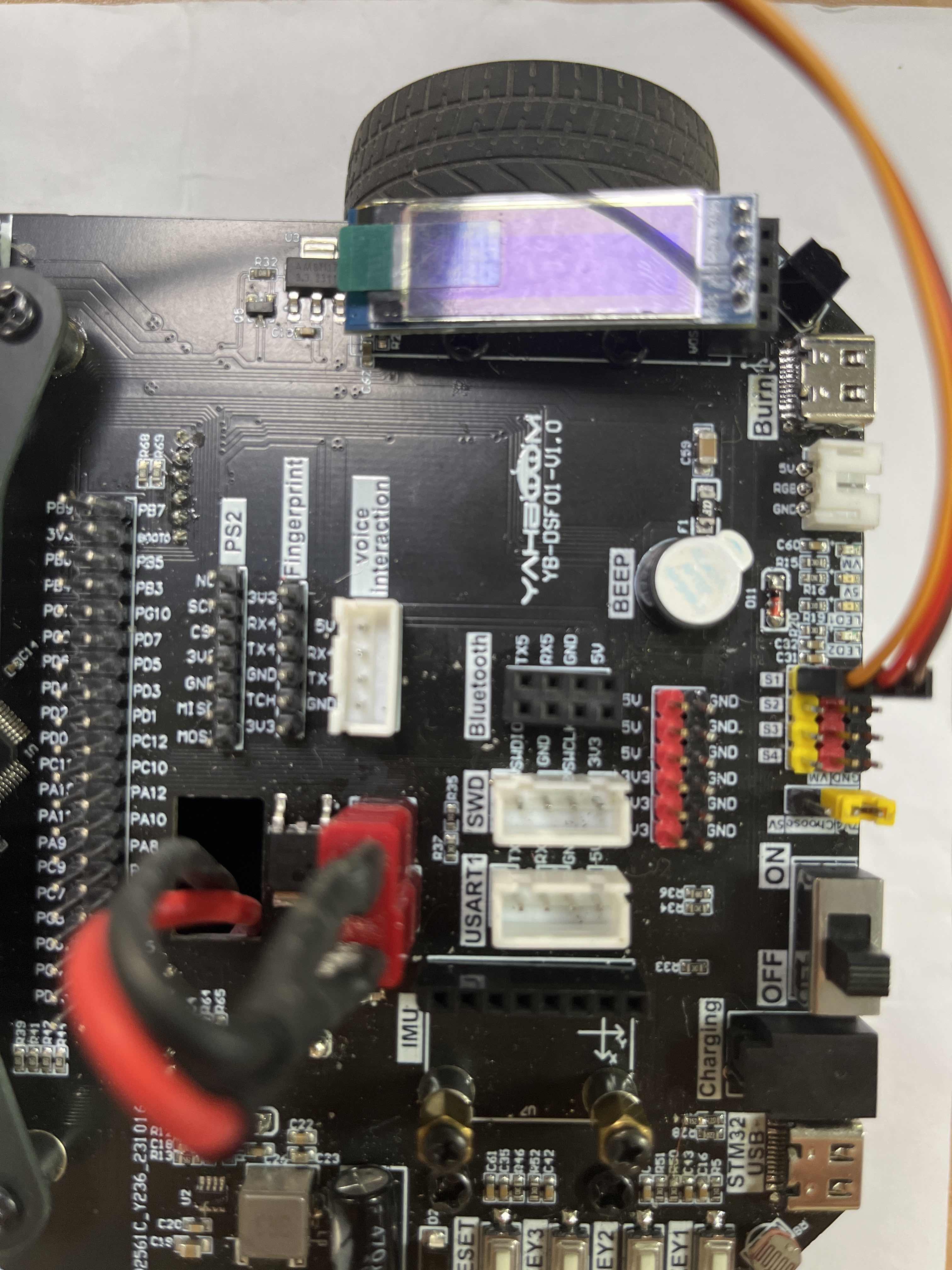
The servo wiring is as follows:
The effect is as follows: