Welcome to myCobot 320 Arm repository
4.Electronic Parameters
Electronic Parameters
1 Overview of the base electrical interface
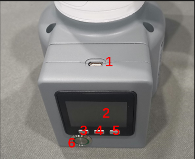
Figure 1 Front view of the base
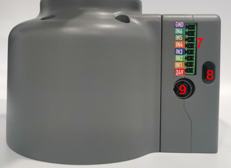
Figure 2 Left side of the base
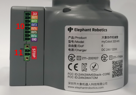
Figure 3 Right side of the base
| Serial number | Interface Name | definition | Function | Remark |
|---|---|---|---|---|
| 1 | Type C | Communication interface | Communicate with PC | Development and use |
| 2 | Screen | show | Use with buttons | |
| 3 | button | Button A | Use with display | |
| 4 | Button B | |||
| 5 | Button C | |||
| 6 | switch | Power switch | Control input power on and off | With light (light turns on when powered on) |
| 7 | DC/IO Interface | GND | GND | |
| IN6 | Digital input signal 1~6 | Input only in NPN mode | ||
| IN5 | ||||
| IN4 | ||||
| IN3 | ||||
| IN2 | ||||
| IN1 | ||||
| 24V | DC24V | |||
| 8 | Type C | Communication interface | Communicate with PC | Development and use |
| 9 | Power DC input interface | DC24V input | DC24V input | |
| 10 | DC/IO Interface | 24V | DC24V | |
| OUT1 | Digital output signal 1~6 | Output only in PNP mode | ||
| OUT2 | ||||
| OUT3 | ||||
| OUT4 | ||||
| OUT5 | ||||
| OUT6 | ||||
| GND | GND | |||
| 11 | Emergency stop interface | STOP | Emergency stop circuit interface |
1.1 Type C: The Type C interface is used to connect and communicate with a personal computer and can be used by developers.
1.2 Screen: The screen is used to display the communication status of myCobot and calibrate the robot to move to the starting point through a 2-inch IPS screen.
1.3 Button A, Button B and Button C are used to operate the screen in a coordinated manner.
1.4 Power switch: The power switch is used to control the main power input. If it is turned off, the controller will also be powered off.
1.5 24V output: Built-in DC24V, available for users.
1.6 Digital Input/Output: Includes 6 digital input signals and 6 digital output signals, which are used to interact with other devices and together with other devices constitute an important part of the automation system.
Digital Input/Output: Includes 6 digital input signals and 6 digital output signals, which are used to interact with other devices and together with other devices form an important part of the automation system.
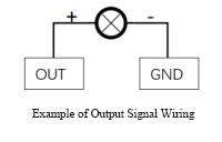
It should be noted that the output signal is in PNP form and the input signal is in NPN form. The following is the external wiring diagram:
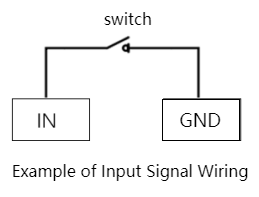
1.7 Power DC input interface: Use KPPX-4P R7BFDC power socket. The 24V 9.2A DC power adapter provided by the manufacturer can also be used to power myCobot320.
1.8 The emergency stop circuit terminal is connected to the emergency stop button box and can be used to control the emergency stop of the robot.
Note : The emergency stop switch must be connected when using the robot, and make sure the emergency stop switch circuit is always connected.
2 Electrical interface at the end of the robot arm
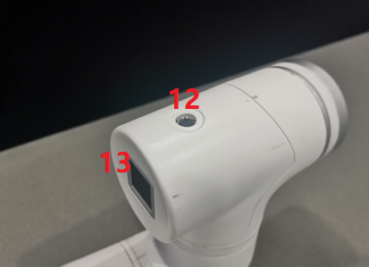
Figure 4 Side view of the end of the robotic arm
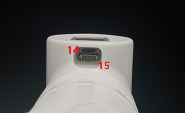
Figure 5 Side view of the end of the robotic arm
| Serial number | Interface Name | definition | Function | Remark |
|---|---|---|---|---|
| 12 | M8 aviation socket | Terminal tool IO interface | Terminal tool IO interface | |
| 13 | Atom | LED + Button | State View/Drag Tutorial | |
| 14 | Type C | Communication interface | Communicate with PC | To update the Atom firmware use |
| 15 | Grove | Developer Use |
2.1 Terminal tool IO interface:
This is a tool input/output diagram, the myCobot 320 robot provides one input and two outputs.
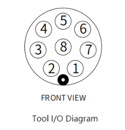
Built-in I/O power supply, voltage 24V, single output maximum 0.2A. Does not support external power supply.
The definition of each tool I/O port is shown in the following table. It should be noted that the input and output of the tool I/O are both PNP type, and the wiring mode is the same as the bottom output interface.
| Serial number | Signal | illustrate | Matching M8 wire color |
|---|---|---|---|
| 1 | GND | DC24V negative | 白 |
| 2 | OUT1 | Tool output interface 1 | 褐 |
| 3 | OUT2 | Tool output interface 2 | 绿 |
| 4 | 485A | Reserved, undeveloped | 黄 |
| 5 | 24V | DC24V positive | 灰 |
| 6 | IN1 | Tool input interface 1 | 粉 |
| 7 | IN2 | Unavailable | 蓝 |
| 8 | 485B | Reserved, undeveloped | 紫 |