Welcome to myCobot 320 Arm repository
4. myBlockly interface display and use of basic functions
myBlockly interface display and use of basic functions
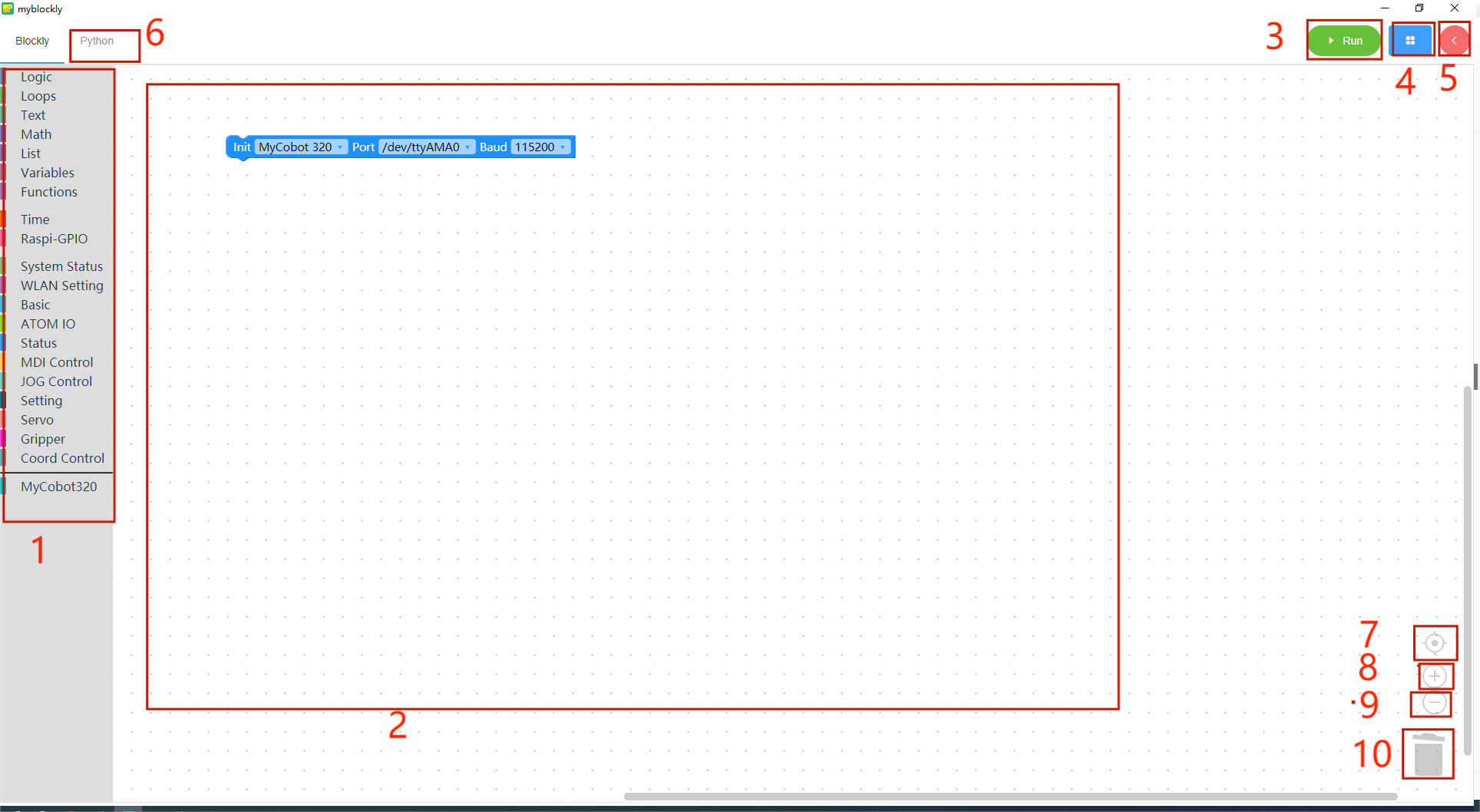
| serial number | illustrate |
|---|---|
| 1 | Toolbox bar: Click on a specific category to select different building blocks |
| 2 | Workspace: You can drag the building blocks of the toolbox to the workspace for use |
| 3 | Run button: Run the code in the workspace |
| 4 | The following menu will pop up after clicking: - Save: Save the current workspace - Load: Load the saved workspace - Settings: Enter the settings page, where you can set the language and theme |
| 5 | After clicking, the control panel will pop up. In the panel, you can quickly control the movement of the robotic arm by clicking "+/-" in the joint control or coordinate control bar. 6 After clicking, you can view the python code generated in the workspace. 7 Center the workspace. 8 Enlarge the workspace. 9 Reduce the workspace. |
| 6 | Click to view the python code generated by the workspace |
| 7 | Center the workspace |
| 8 | Zoom into workspace |
| 9 | Reduce work area |
| 10 | Trash can: Drag the building blocks in the workspace here to delete the building blocks; click the trash can at the same time to view and restore the deleted building blocks |
Program running
Before officially starting programming, be sure to select the corresponding machine model, otherwise it will easily cause hardware damage.
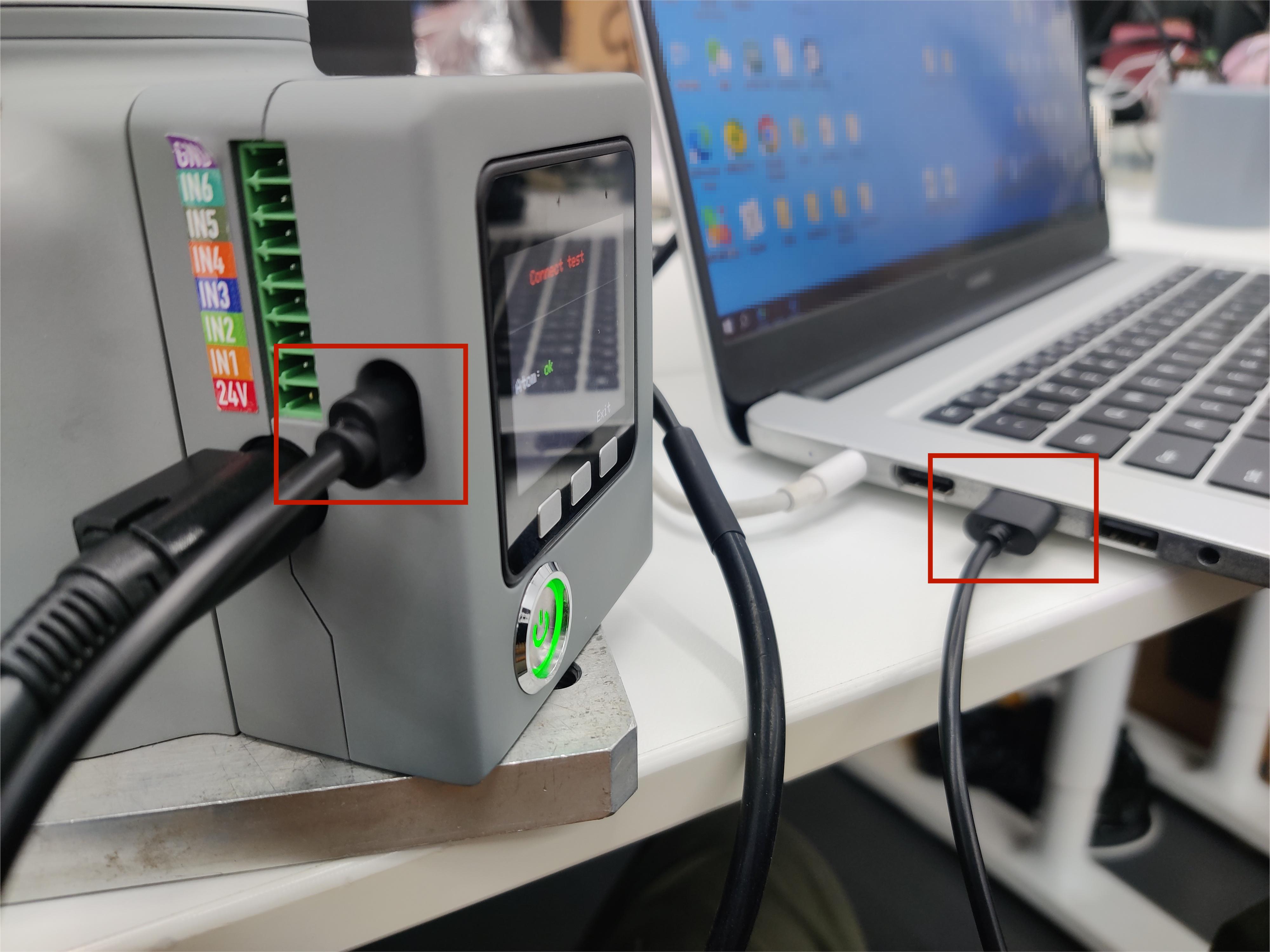
First connect myCobot 320 M5 to our computer through USB data cable,

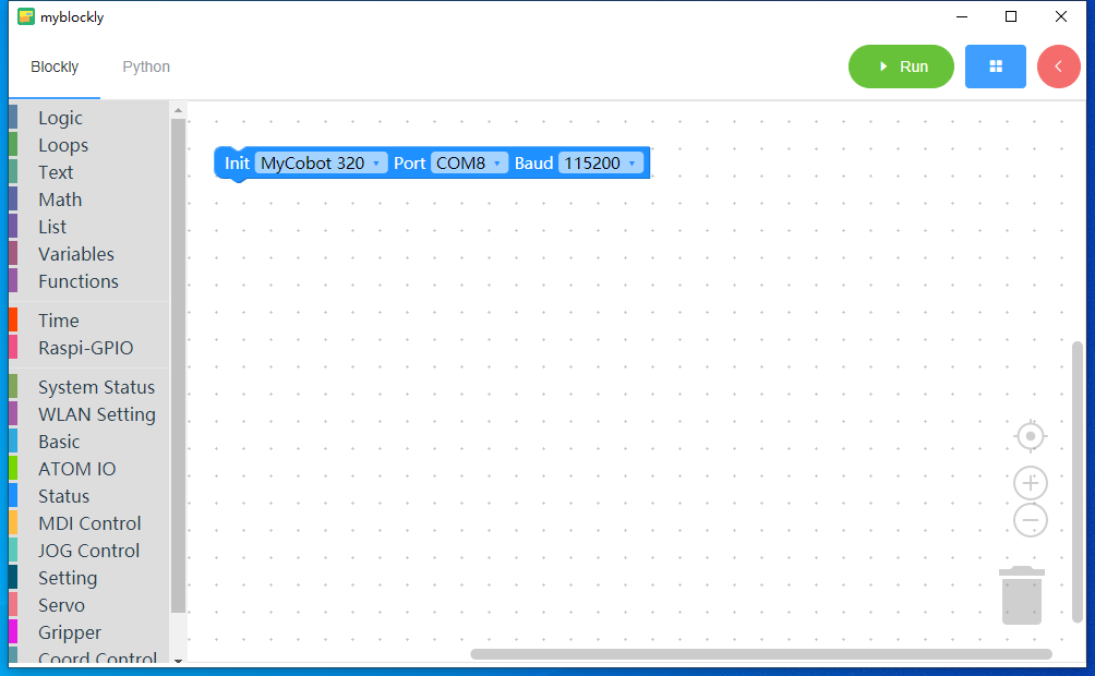
And then we select the initialization model as myCobot 320, the port connected to my computer is COM8, and the baud rate is 115200
The com port number is not fixed, you need to choose according to the actual port number of the individual PC connection How to choose the corresponding port number: by unplugging the usb cable on the side of the M5stack to see if there is any change in the corresponding port number to choose, unplugged in both cases there is a change in the com port is the machine's communication serial port.
small case
We use building blocks to implement such a small case: let the robotic arm return to the zero point, and then move a joint 30 degrees.
Make sure robot is power on
Click the
Statuscategory in the toolbox, select thePower Onbuilding block and drag it to the workspace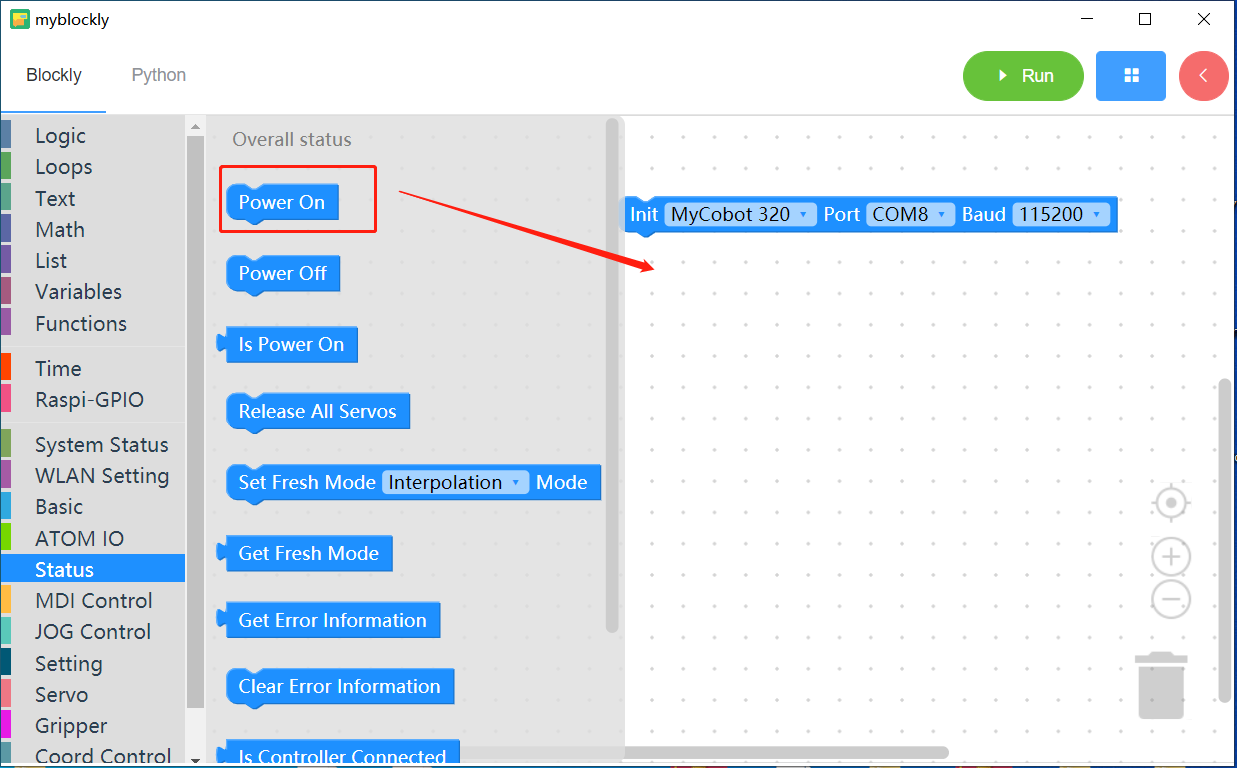
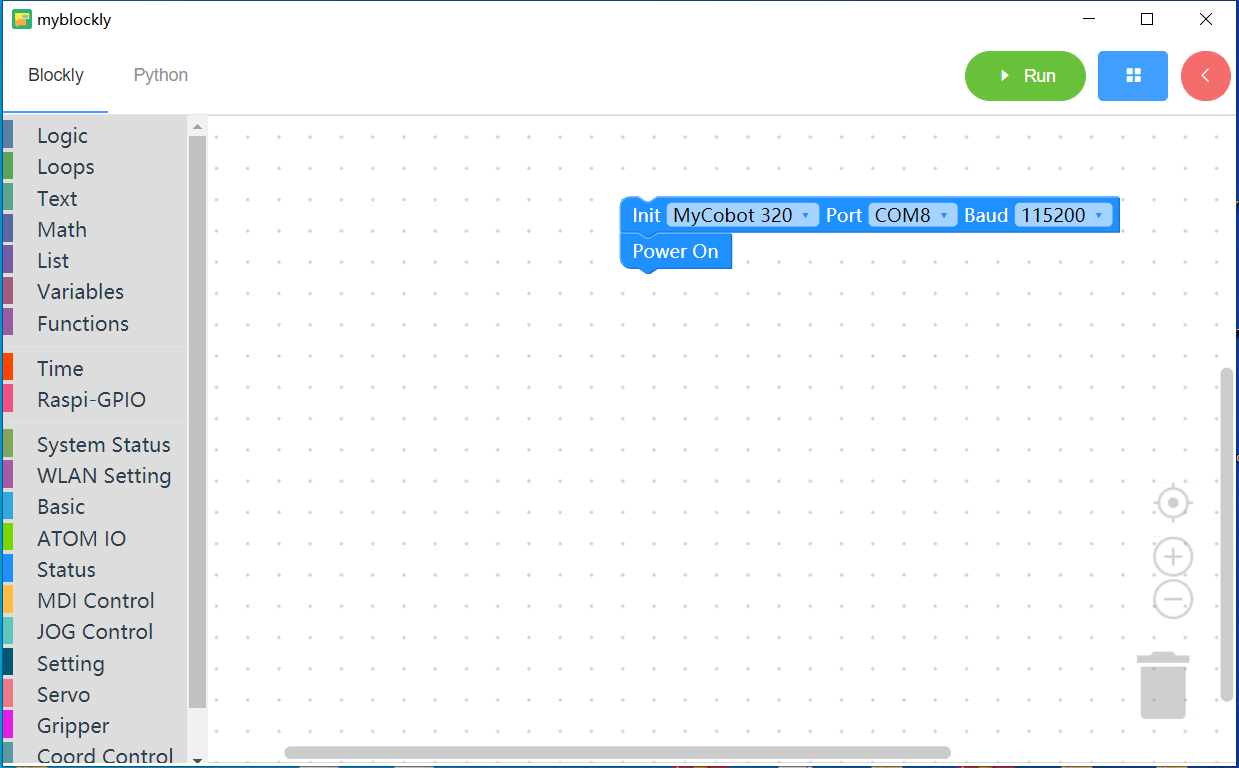
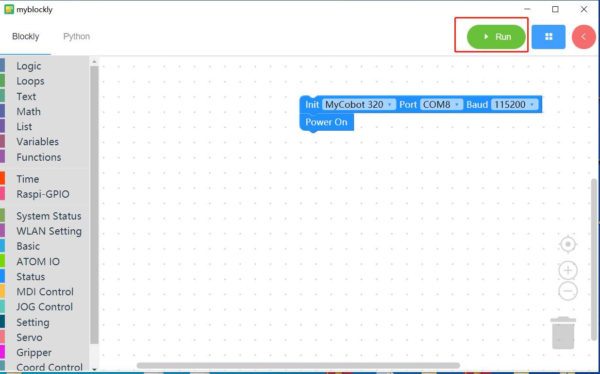
Click to Run button
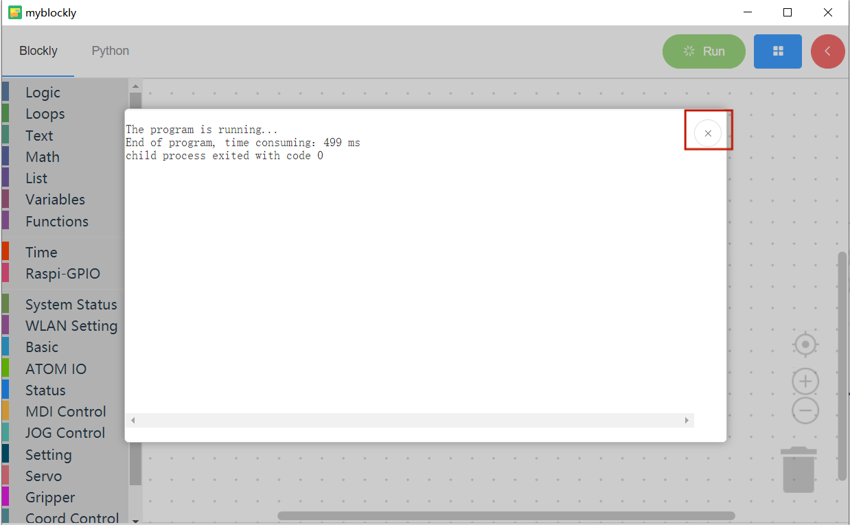
If the End of program text appears in the popup, the program is finish.
Check whether the device is successfully powered on.
If the joint of the machine cannot be broken by hand, it is successfully powered on
And please click the X button to close pop-up window
Let's start with our little case study
Click the
MDI Controlcategory in the toolbox, select theSet Anglebuilding block and drag it to the workspace
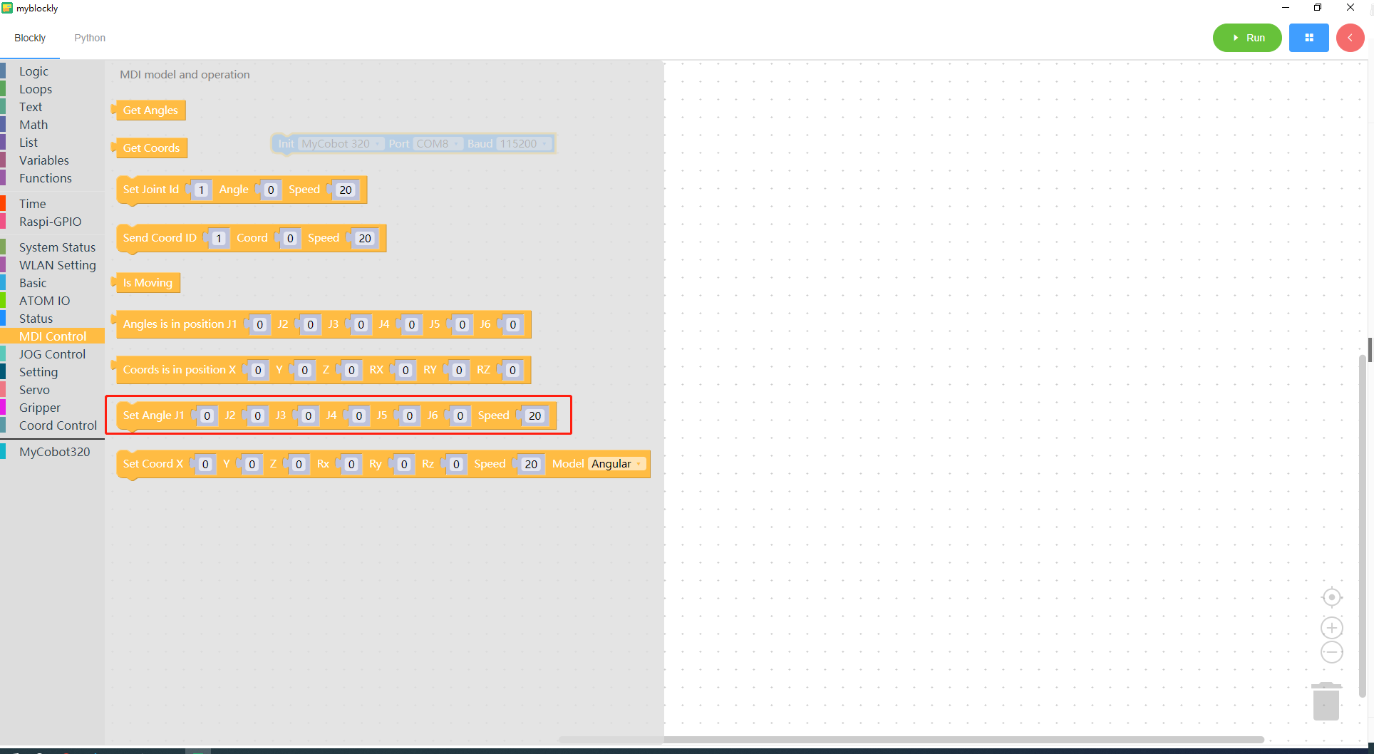
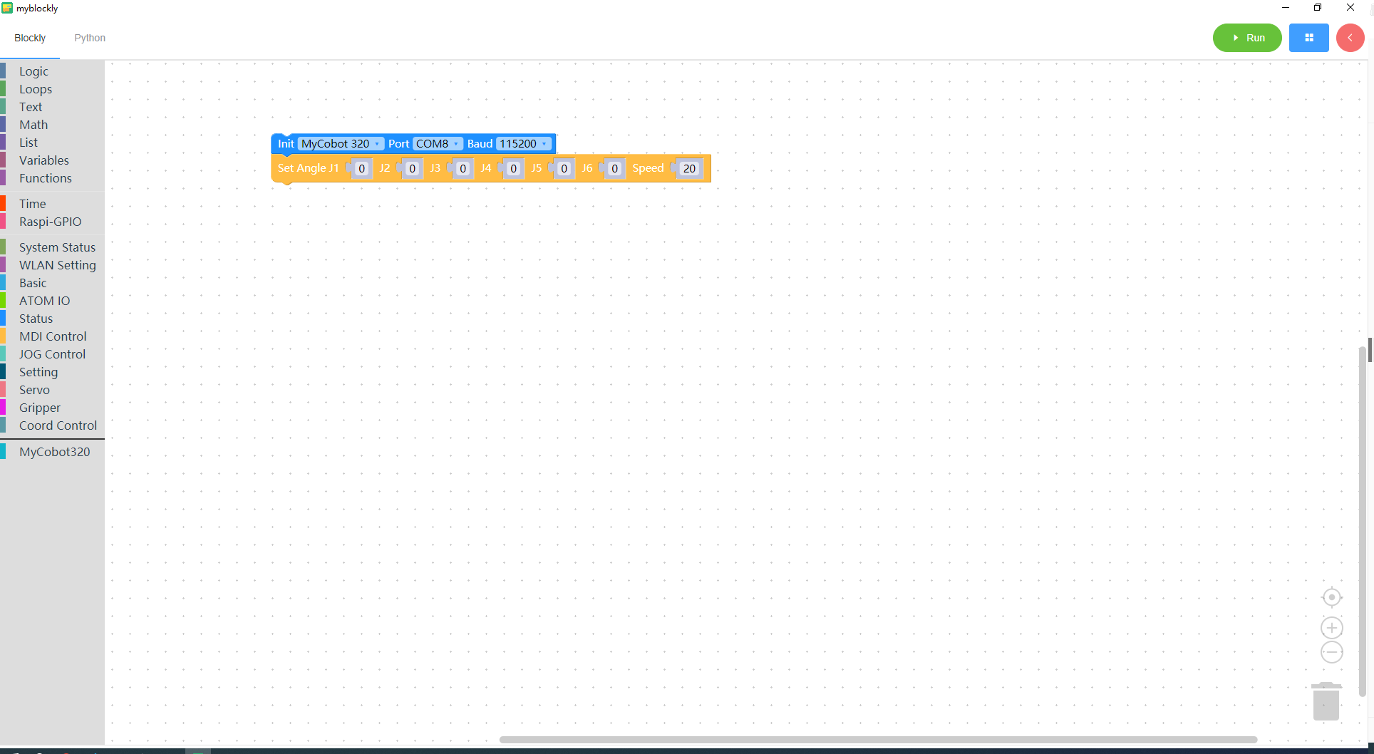
Click the
Timecategory in the toolbox, select theSleepbuilding block and drag it to the workspace; click the mouse on the input box and change the input value of the building block to5
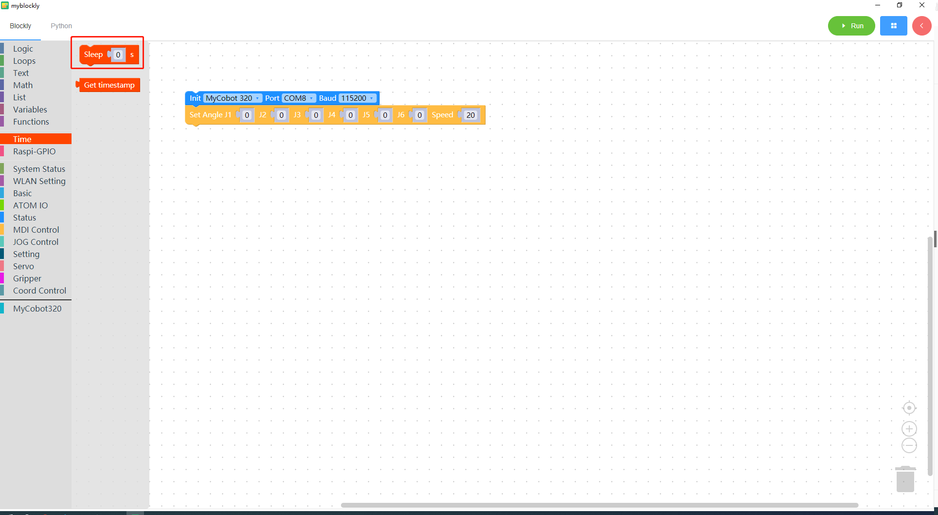
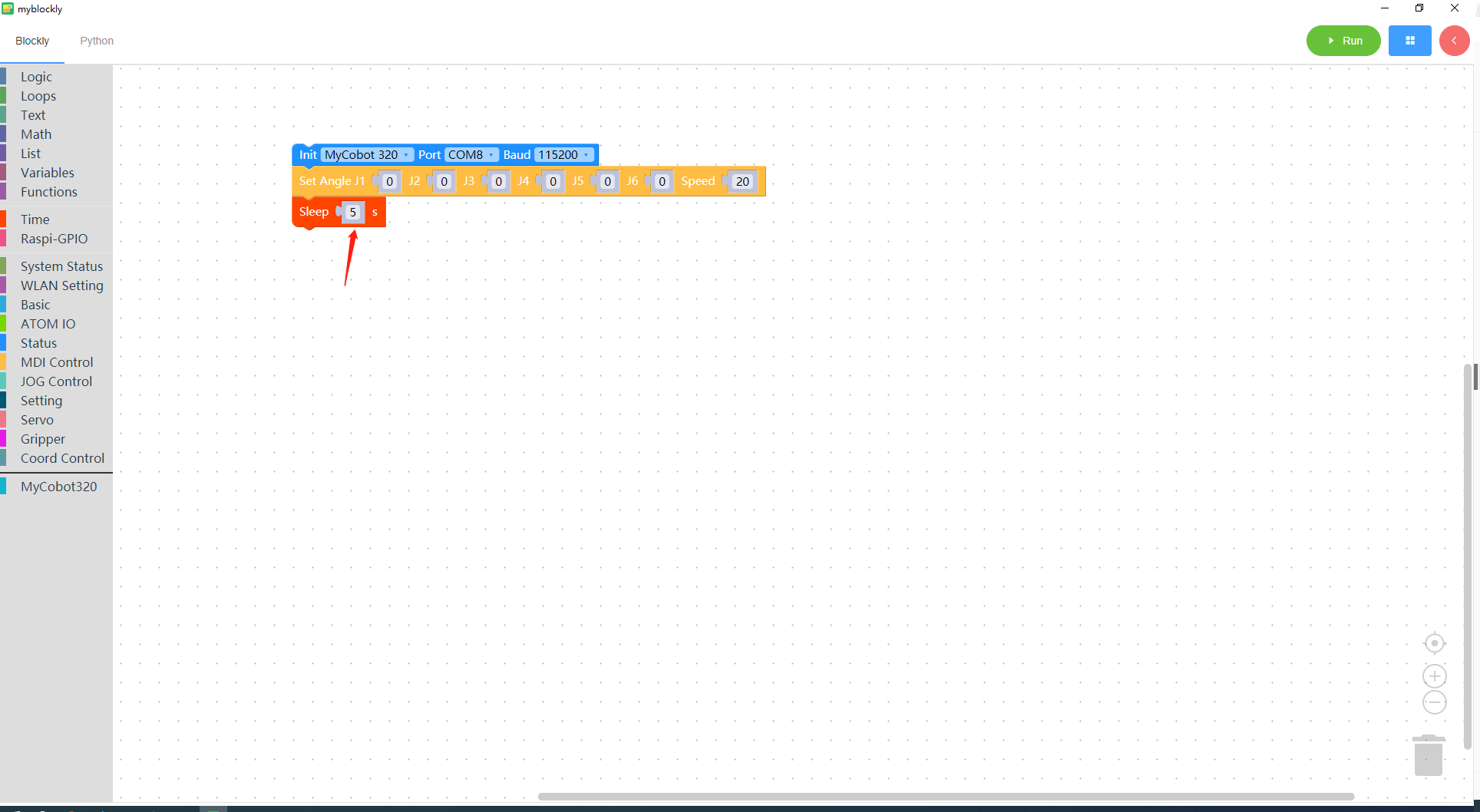
Click the
MDI Controlcategory in the toolbox again, select theSet Anglebuilding block and drag it to the workspace; at the same time, change the input value ofJ1to 30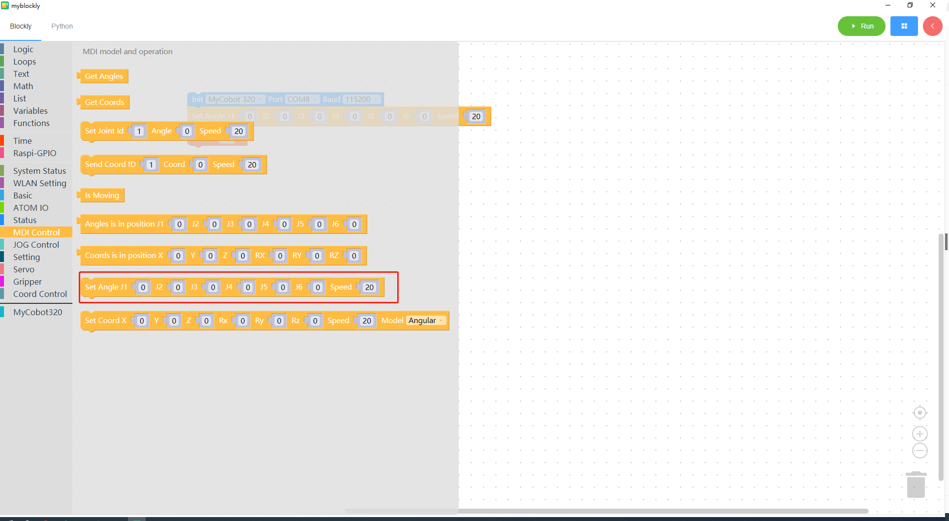
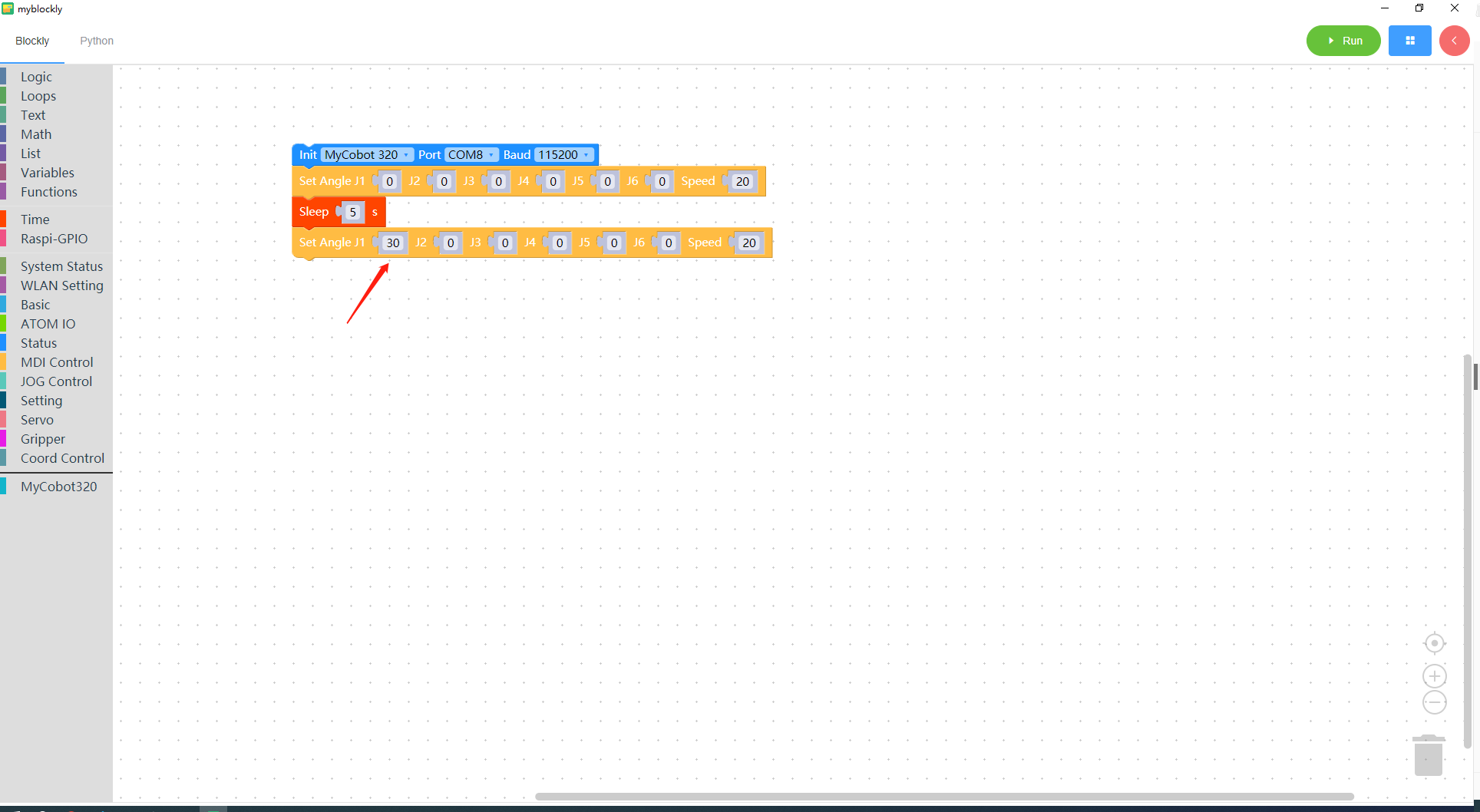
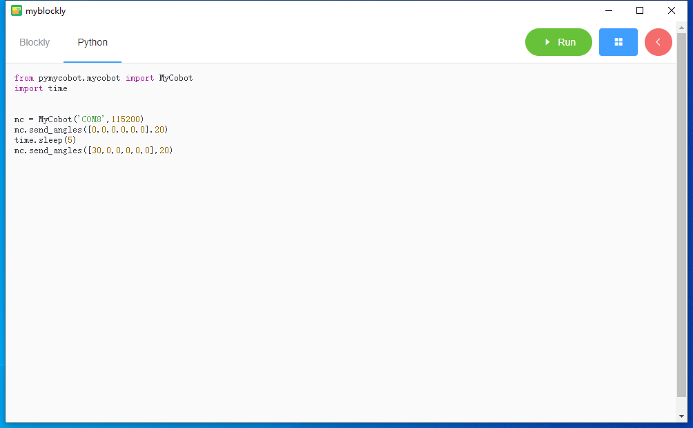
Click the "Python" option in the upper left corner to view the corresponding Python code, as shown in the figure below.
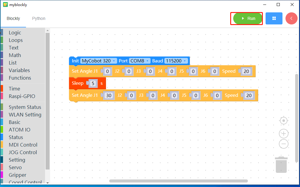
Click the
Runbutton to run the code and observe the movement of the robotic arm.
Program is running
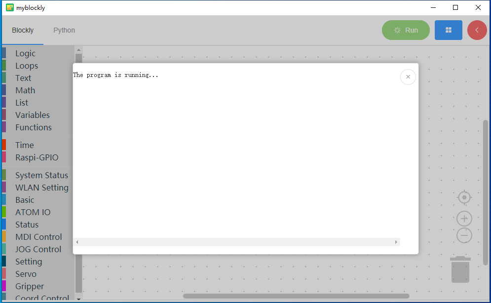
The program ends
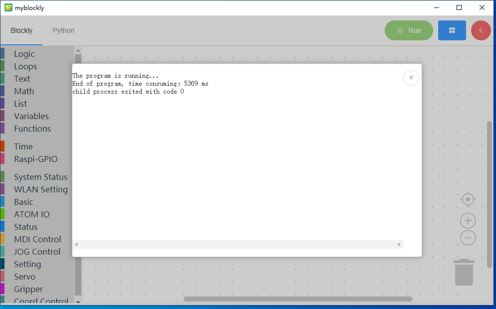
Click the
xbutton in the upper right corner of the run pop-up window to close the pop-up window
Notice:
The program to operate the robot arm takes time to complete, so a `sleep' module needs to be connected after one action to give the robot arm time to move before proceeding with the next movement. (You decide the time required based on the situation. By default, the robotic arm is set to run myBlockly for a minimum sleep time of no less than 0.5 seconds.) Otherwise, the robotic arm will not be able to achieve the ideal movement.
When the program cannot run, please check whether the small toolbar is disconnected (as shown in the figure below).
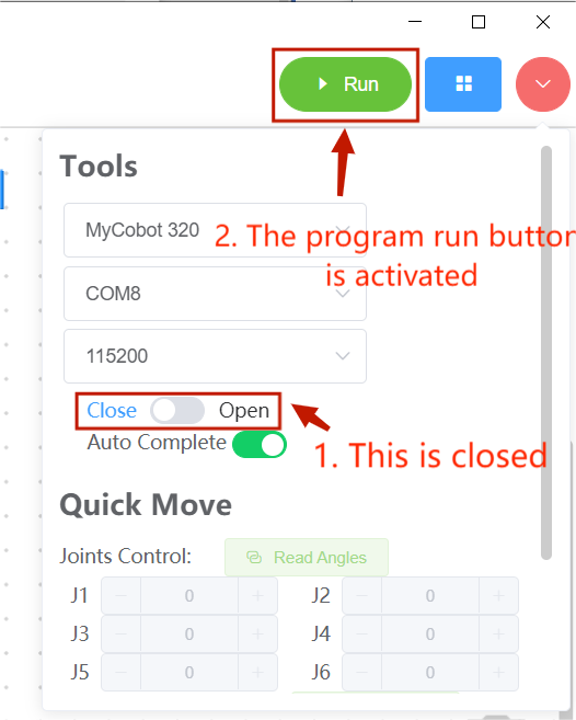
Using the control panel
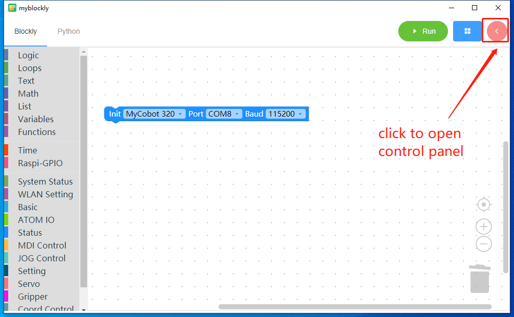
When using the control panel to control the machine, be sure to select the corresponding machine model, otherwise it will easily cause hardware damage.
Here we choose the model myCobot 320 ,Port is COM8,and the baud rate 115200
Note: The port that is actually connected to the computer shall prevail.
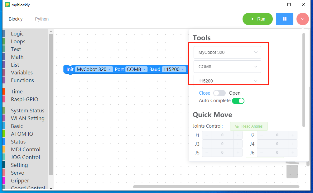
After selecting the model and port, click the Open button to connect the robotic arm.
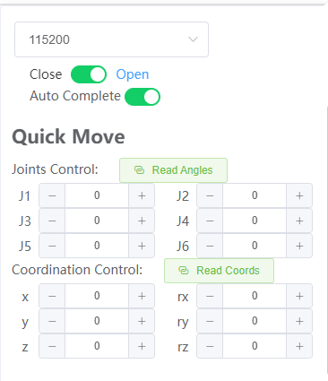
Read angles and coordinates
Click the read angle button to read the machine angle value
Click the Read Coordinates button to read the machine coordinates
You can control the movement of the robot arm joints by clicking the mouse, long pressing the -/+ button, and modifying the values.
Program saving and loading
MyBlockly's program is saved in *.json format. Click the blue box in the upper right corner of the interface. When the "Save" option appears, click it to save the program.
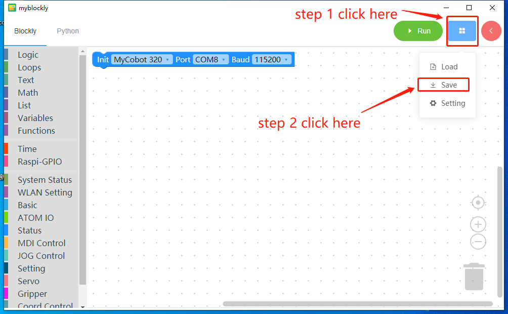
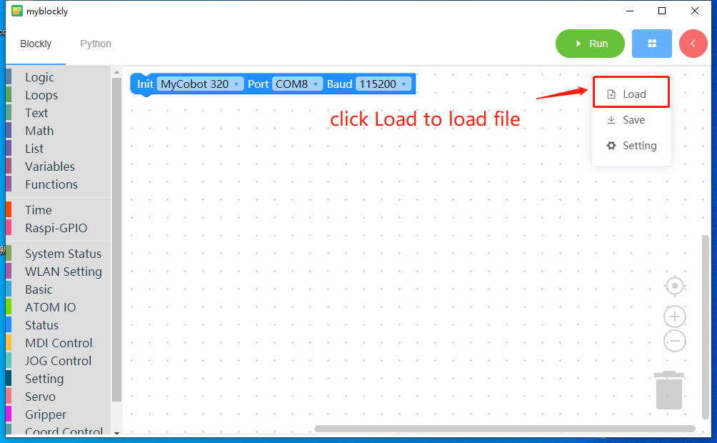
Also click the blue box and click the "Load" option to import the saved program.