yahboom
HomeLearn
Solution
Blog
Online Store
About Us
EN/中文
myCobot 320 Arm📖
1.Product Feature
  • 1.Functional Parameters
  • 2.Controller Parameters
  • 3.Structural Parameters
  • 4.Electronic Parameters
  • 5.Coordinate System
  • 6.Introduction of Adaptive Gripper
  • 7.Introduction of force-controlled gripper
2.Common Problem
  • 1.how to ask
  • 2.driver
  • 3.software
  • 4.hardware
3.First Install and Use
  • 1.Product Standard List
  • 2.Product Unboxing Guide
  • 3.Power-on Test Guide
4.Basic Application
1. miniRoboFLow
  • 1. miniRoboFLow
  • 2. Drag & Play
  • 3. Joint Calibration
  • 4. Computer Connect
  • 5. Robot Information
2.1 myblockly
  • 1. What is myBlockly
  • 2. Preparations before using myBlockly
  • 3. myBlockly download and install
  • 4. myBlockly interface display and use of basic functions
  • 5. Control RGB light panel
  • 6. Control the robotic arm to return to the origin
  • 7. Control single joint movement
  • 8. Control multiple joints
  • 9. Use of adaptive grippers
  • 10. Use of force-controlled grippers
  • 11. Q&A
  • 12. API
3. Firmware Description
  • 1.Firmware Description
  • 2.Burn Firmware
2.2 myStudio
  • 1. myStudio
  • 2. myStudio environment setup
  • 3. Install driver
  • 4. Burn and update firmware
5.Mobile APP control
  • Mobile APP control
6.SDK Development
1.Development Environment Construction
  • 1.Development Environment Construction
2.Python
  • 1.What is Python
  • 2.Environment Building
  • 3.Python API usage instaructions
  • 4.TCP IP
  • 5.Drag to teach
  • 6.Use Cases
  • 7.Use of adaptive grippers
  • 8.Use of force-controlled grippers
3.ROS1
  • 1.ROS
  • 2.Environment Building
  • 3.ROS basics
  • 4.Rviz use
  • 5.Basic function case
  • 6.Use of adaptive grippers
  • 7.Use of force-controlled grippers
4.ROS2
  • 1.ROS2 introduction
  • 2.Environment Building
  • 3.ROS2 basics
  • 4.Rviz2 use
  • 5.Basic function case
5.C Sharp(C#)
  • 1.C#
  • 2.Environmental construction
  • 3.Mechanical control
  • 4.myCobot API
  • 5.Use Cases
  • 6.Use of adaptive grippers
6.c plus plus (C++)
  • 1.C++
  • 2.CPlus Download
  • 3.build
  • 4.API
  • 5.example
7.Arduino
  • 1.Arduino
  • 2.Arduino Download
  • 3.API
  • 4.example
  • 5.Use of adaptive grippers
8.Serial communication
  • 1.Serial communication
  • 2.Use of force-controlled grippers
7.Documents Download
  • 1.Product Brochure
  • 2.Software and Source Code
  • 3.System lnformation
Download
  • 3D_Model_File
  • Android Mobile APP
  • Manual
Download ZIP

Welcome to myCobot 320 Arm repository

3. Joint Calibration

Robot arm Calibration
img-1This operation has been performed before the default robot is delivered. You do not need to repeat the operation. Incorrect use of this function may cause damage to the robot. If your robot works without abnormal conditions, please do not use it. Thank you for your cooperation.

Before performing a zero calibration, allow the machine to return to zero and check for any deviation in the zero attitude. If there is, then perform zero calibration; if not, zero calibration is not required. You can use pythonAPI to make the joints reach the zero position: send_angles(degrees, speed), where degrees is a floating-point list with [0,0,0,0,0,0] representing the zero position of the six joints, and speed is the speed at which the joints are moving, which takes the values of 0 to 100.

img-1

Calibrating the robot arm is the precondition for precise control of the robot arm, and setting joint zero and initializing the potential of the motor are basic jobs for subsequent advanced development.

Different types of equipment have different operating methods. They have the approximate steps below:

  • Burn the latest version of atomMain for Atom, and the minirobot for M5Stack-basic.

  • Choose the Calibration function (It is unnecessary to burn Basic for micro-CPU devices)

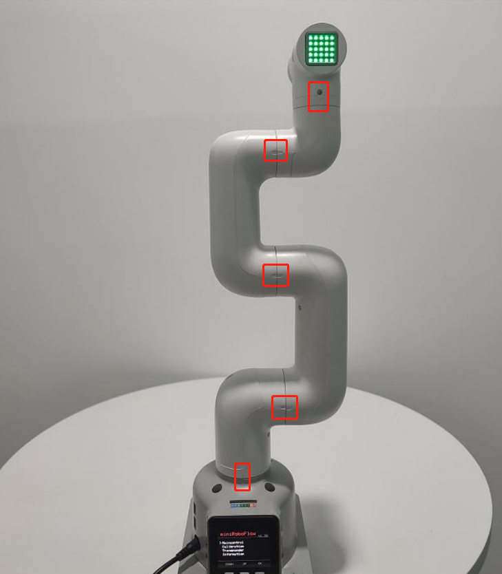
  • move all joints of the robot arm to their zero positions (align them with the scale line of zero positions)

  • Press the calibration button and get started with robot arm calibration

  • press the test button to test the zero positions

  • press the exit button to exit this function

In this chapter, we will teach you how to calibrate the robot arm and to test and verify the joints.

Calibration Demonstration

1 Applicable Robotic Arms

  • myCobot 320 M5

2 Steps to Operate the Arm

Step1:

  • Please confirm that you are aware of the product safety instructions and ensure that the device has been connected with cables as described in Chapter 4.

  • Turn on the power switch and ensure that the emergency stop switch is connected and not pressed.

  • Confirm that the Atom LED light board at the robot's end-effector is illuminated and that the robot's joints have torque output, making the joints unable to rotate.

Step 2: Press OK Select Calibration.

img-1

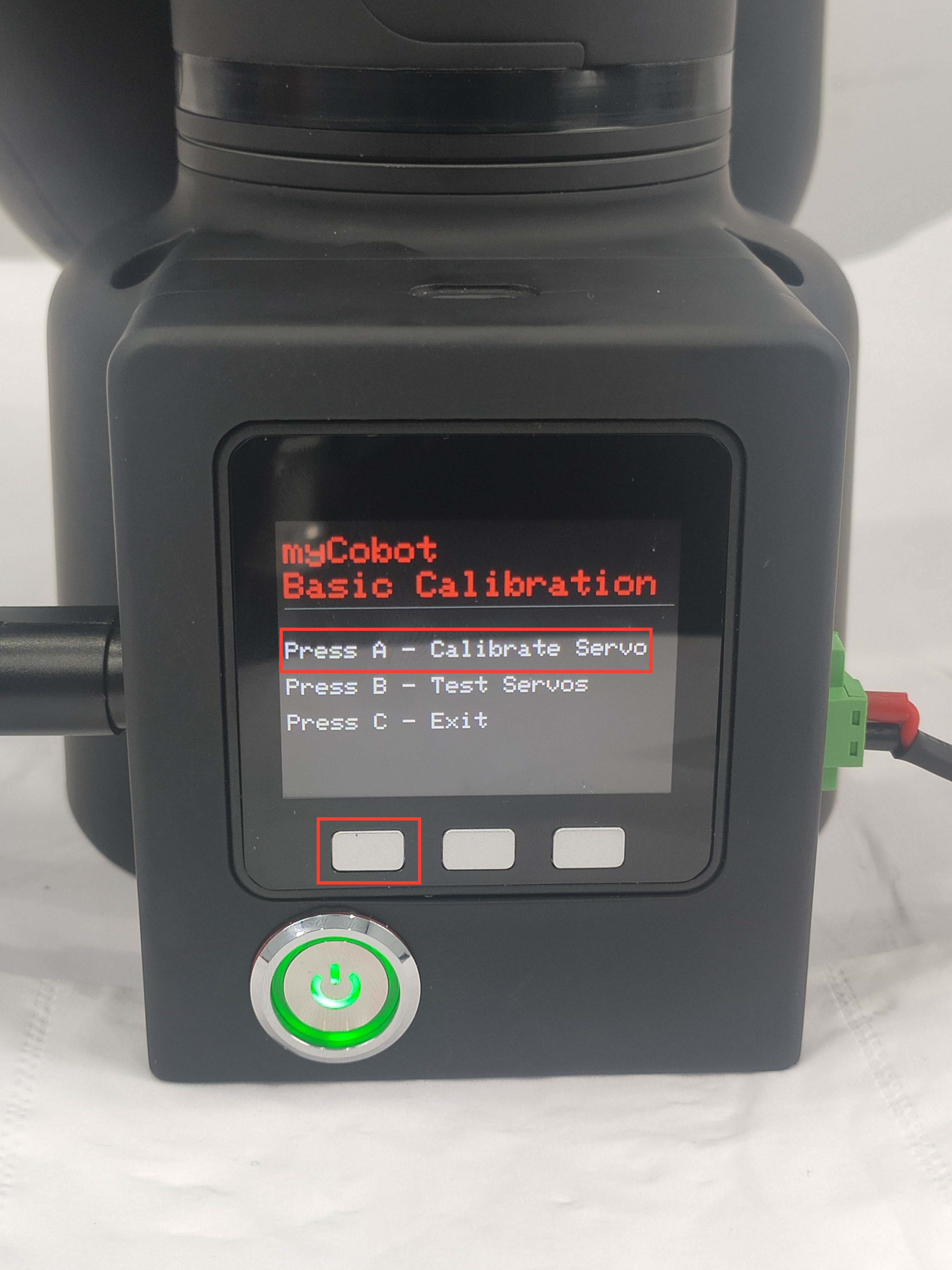
Step 2: Press A to start robot arm calibration.
img-1

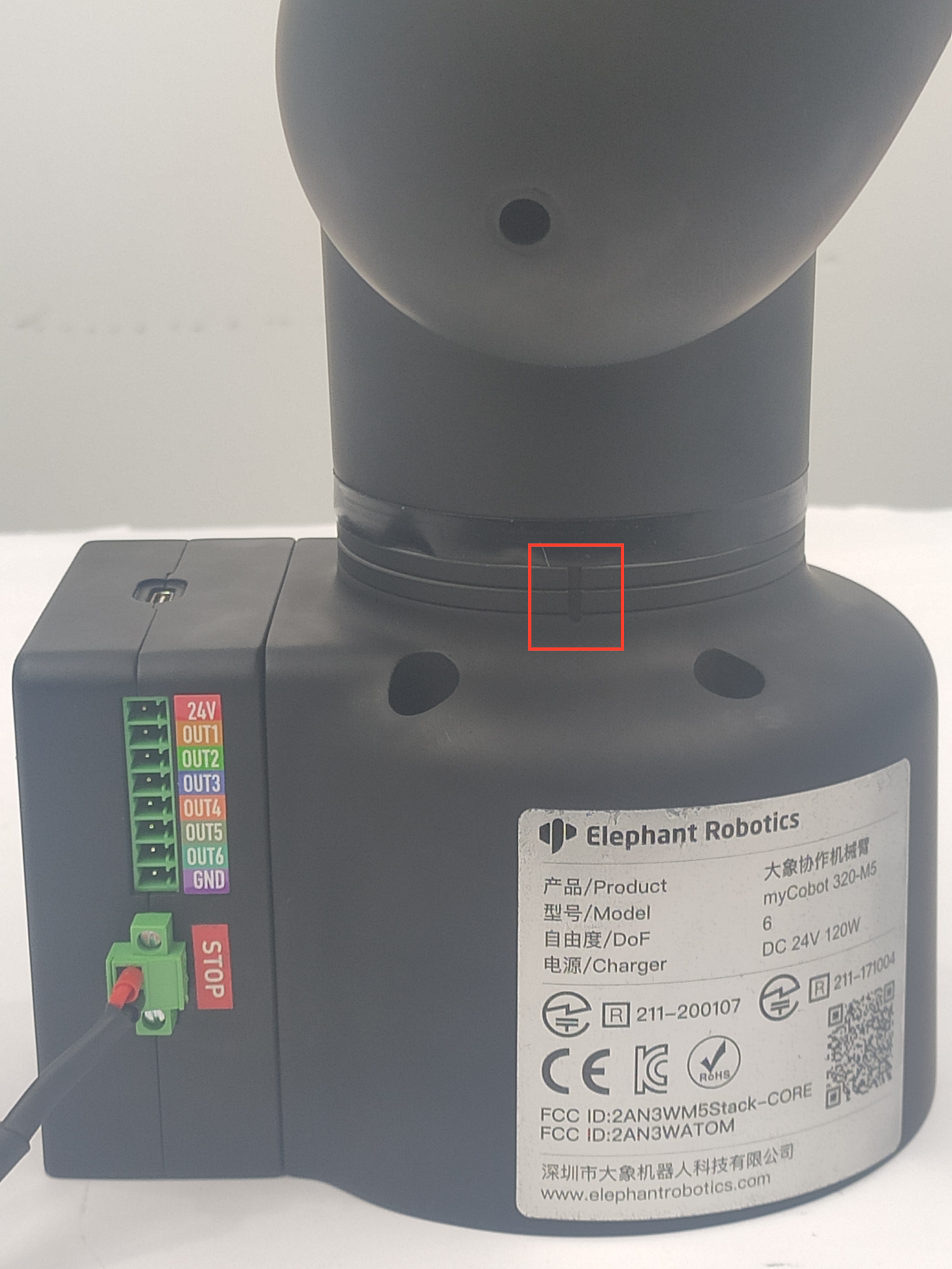
Step 3: Align each joint with zero-position line in sequence.
img-1

Step 4: After finishing calibrating all joints, a signal Already Calibrate all !! emerges on the screen.

img-1

Calibration results

img-1

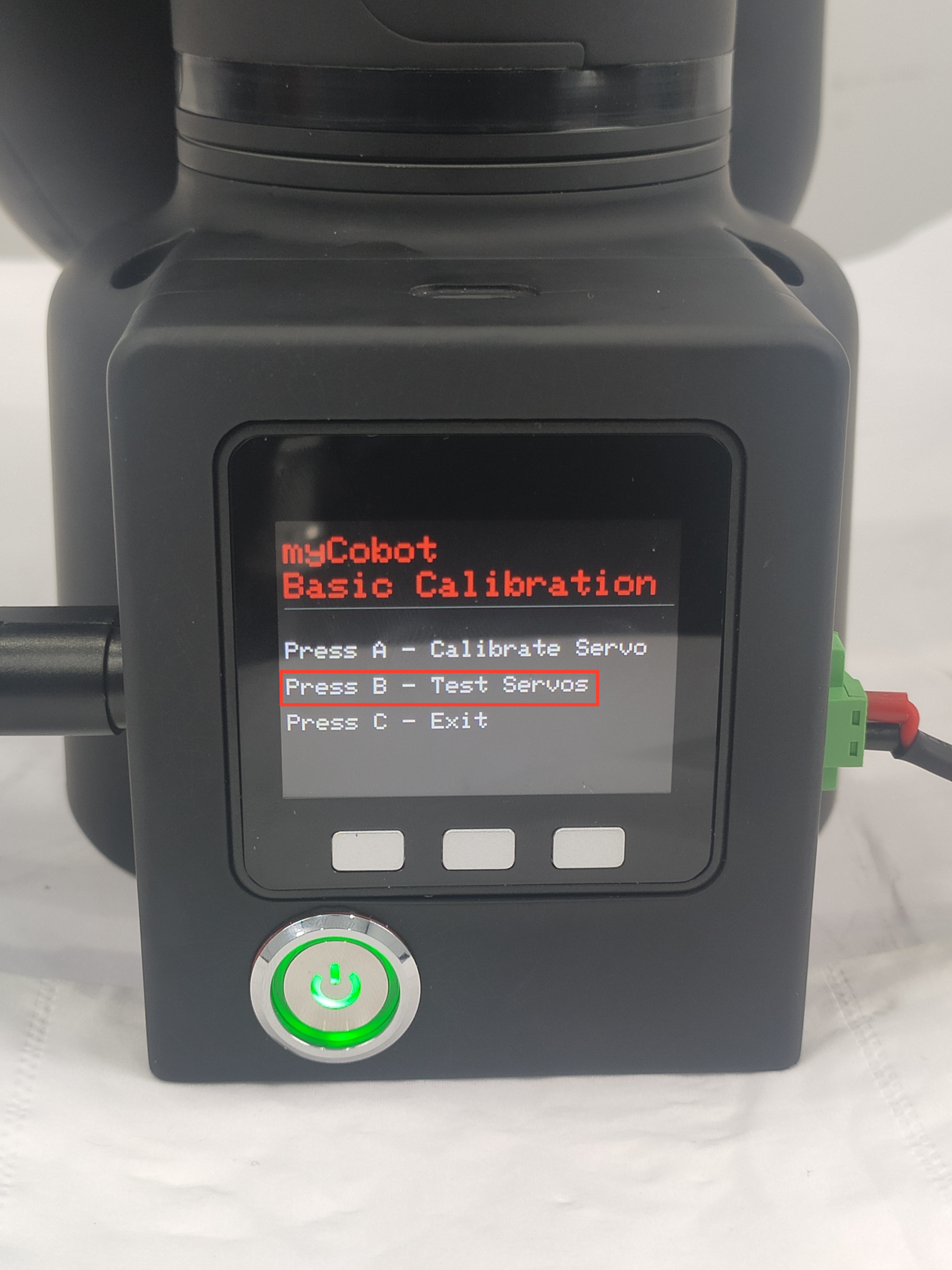
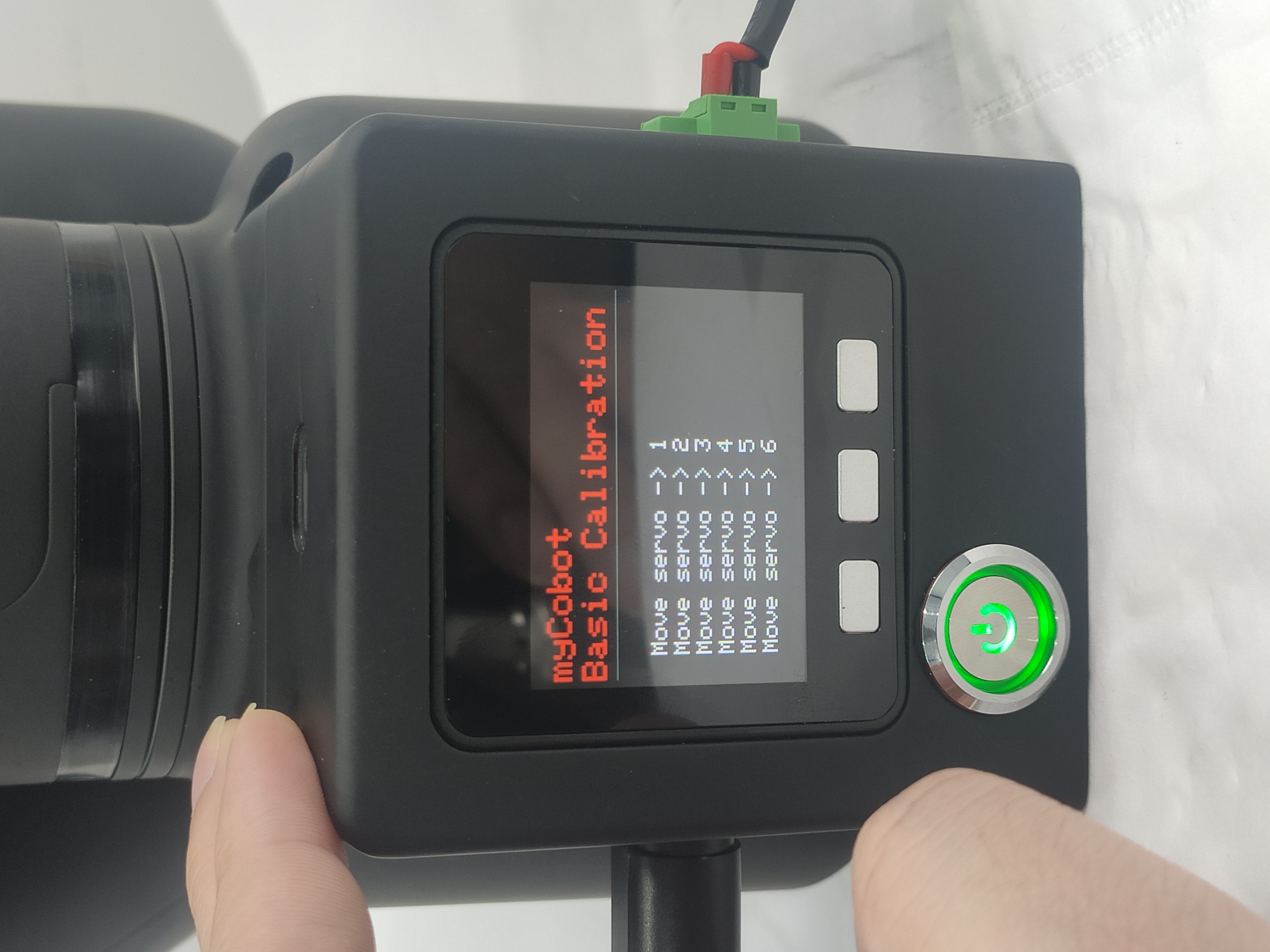
Step 5: Press EXIT to stop calibration and then press B to test the zero positions of all joints.

The joints will rotate positively and negatively by 15-30 degrees and return to the zero position.
img-1

img-1

Step 6: Press C to exit this function. Calibration completes.

img-1

Drag & Play
Computer Connect

COMPANY

  • About us
  • Team Style
  • Blog

LEARNING & EXPLORATION

  • Tutorials
  • Edge AI hardware
  • Educational robots
  • Embedded intelligent hardware

WHERE TO BUY

  • Yahboom Online Store
  • Amazon
  • Alibaba
  • AliExpress
  • Mercado

TECHNOLOGY SUPPORT

  • Email: support@yahboom.com

BE A DISTRIBUTOR

  • Email: sales@yahboom.com
QR Code

Copyright © 2017-2026 Yahboom. All Rights Reserved.

EN/中文