Welcome to Self-balancing Robot Car repository
04.Button control(EXTI)
Button control
Button controlHardware connectionControl principleSoftware configurationPin definitionSoftware codeControl functionExperimental phenomenon
The tutorial demonstrates that the button controls the buzzer to sound, and the LED keeps flashing.
The tutorial only introduces the standard library project code
Hardware connection
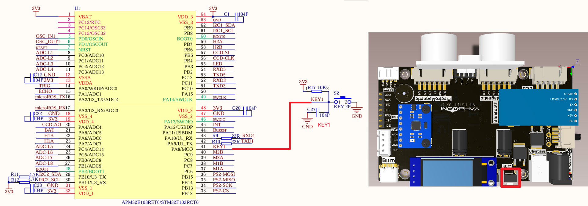
| Peripherals | Development board | Description |
|---|---|---|
| KEY1 | PA8 | One end of KEY is connected to the PA8 pin, and the other end is connected to GND |
Control principle
Trigger an external interrupt through a button, and switch the buzzer sound state according to the triggered button.
| Control pin | Read level | LED effect |
|---|---|---|
| PA8 | Read low level | Switch buzzer sound state |
| PA8 | Read high level | Do not switch buzzer sound state |
NVIC (Nested Vector Interrupt Controller)
NVIC controls the interrupt-related functions of the entire chip and provides a reliable interrupt processing mechanism for the system.
Interrupt priority
Preemption priority: Preemption priority is used to determine the relative priority between interrupts. When an interrupt with a high preemption priority occurs, it can interrupt the interrupt with a low preemption priority being executed;
Response priority: When multiple interrupt sources have the same preemption priority, the interrupt with a high response priority will be processed first, and will not be interrupted by the interrupt with the same preemption priority but a low response priority.
EXTI (External Interrupt)
The external interrupt/event controller consists of 19 edge detectors that generate event/interrupt requests.
Each input line can be independently configured with input type (pulse or hang-up) and corresponding trigger event (rising edge or falling edge or both edges), and each input line can be independently masked.
External interrupt/event line image
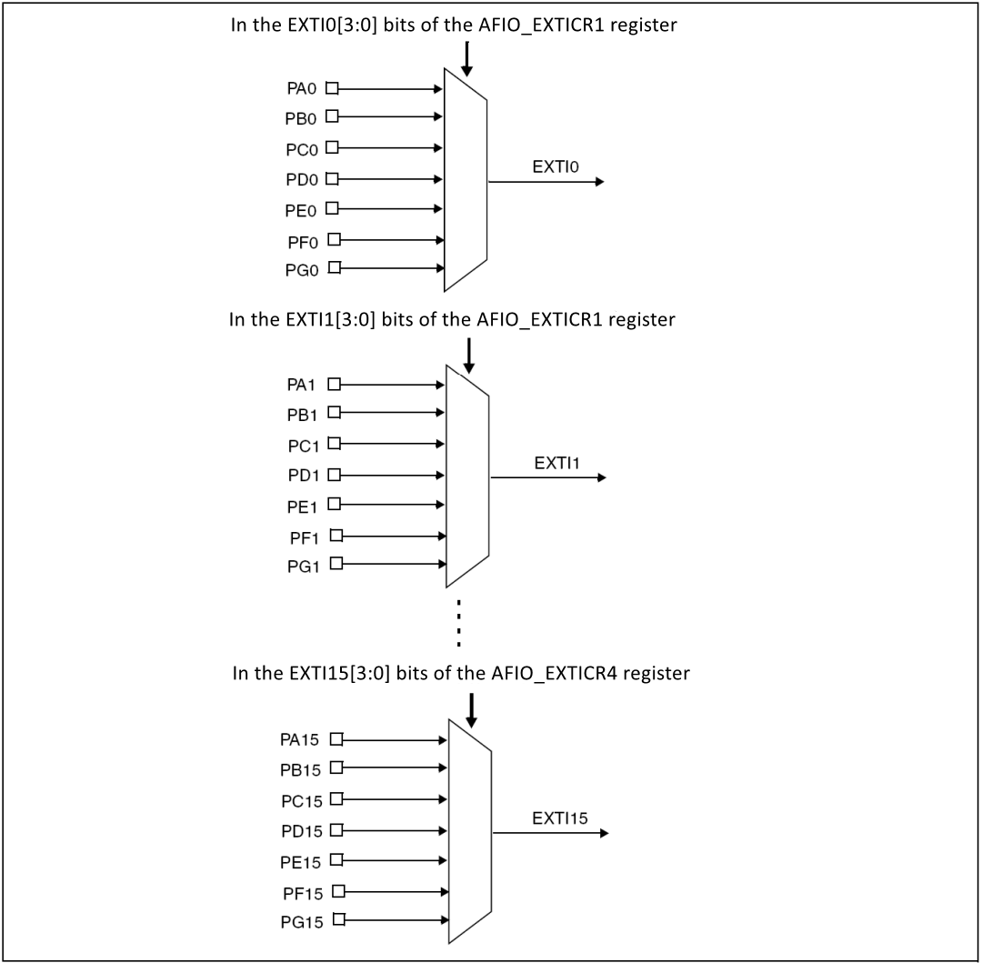
xxxxxxxxxxEXTI0~EXIT4 have independent interrupt channelsEXTI5~EXIT9 share the same interrupt channel: EXTI9_5_IRQEXTI10~EXIT15 share the same interrupt channel: EXTI15_10_IRQ
Key corresponding external interrupt trigger mode: falling edge trigger
Software configuration
Pin definition
| Main control chip | Pin | Main function (after reset) | Default multiplexing function | Redefine function |
|---|---|---|---|---|
| STM32F103RCT6 | PA8 | PA8 | USART1_CK/TIM1_CH1/MCO |
Software code
The default function of the PA8 pin is a normal IO pin function.
xxxxxxxxxxProduct supporting data source code path: Attachment → Source code summary → 1.Base_Course → 4.KEY
Control function
The tutorial only briefly introduces the code, and you can open the project source code to read it in detail.
Key1_GPIO_Init
xxxxxxxxxxvoid Key1_GPIO_Init(void){GPIO_InitTypeDef GPIO_InitStructure;EXTI_InitTypeDef EXTI_InitStructure;NVIC_InitTypeDef NVIC_InitStructure;RCC_APB2PeriphClockCmd(KEY1_GPIO_CLK, ENABLE);GPIO_InitStructure.GPIO_Pin = KEY1_GPIO_PIN;GPIO_InitStructure.GPIO_Mode = GPIO_Mode_IPU;GPIO_Init(KEY1_GPIO_PORT, &GPIO_InitStructure);EXTI_InitStructure.EXTI_Line=EXTI_Line8;EXTI_InitStructure.EXTI_Mode = EXTI_Mode_Interrupt;EXTI_InitStructure.EXTI_Trigger = EXTI_Trigger_Falling;EXTI_InitStructure.EXTI_LineCmd = ENABLE;EXTI_Init(&EXTI_InitStructure);NVIC_InitStructure.NVIC_IRQChannel = EXTI9_5_IRQn;NVIC_InitStructure.NVIC_IRQChannelPreemptionPriority = 0x02;NVIC_InitStructure.NVIC_IRQChannelSubPriority = 0x01;NVIC_InitStructure.NVIC_IRQChannelCmd = ENABLE;NVIC_Init(&NVIC_InitStructure);}
EXTI9_5_IRQHandler
xxxxxxxxxxvoid EXTI9_5_IRQHandler(void){if(KEY_INT==0){EXTI->PR=1<<8; // Clear interrupt flagBEEP_BEEP = !BEEP_BEEP;}}
Experimental phenomenon
The KEY.hex file generated by the project compilation is located in the OBJ folder of the KEY project. Find the KEY.hex file corresponding to the project and use the FlyMcu software to download the program into the development board.
After the program is successfully downloaded: the LED switches on and off every 500ms; each time the KEY1 button is pressed, the sound state will be switched.