Welcome to Self-balancing Robot Car repository
09.Advanced Timer(TIM)
Advanced Timer (TIM)
Advanced Timer (TIM)Hardware connectionControl principlePin definitionSoftware codeControl functionExperimental phenomenon
Tutorial demonstrating advanced timer (TIM8) PWM driving motor.
xxxxxxxxxxThe tutorial only introduces the standard library project code
Hardware connection
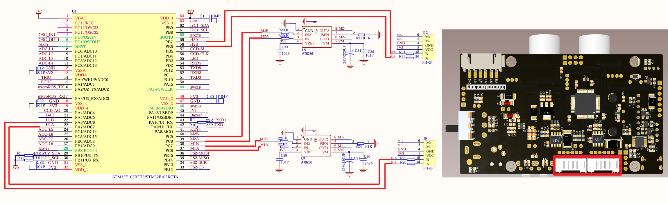
Since we have configured a special connection line, we only need to install it to the corresponding interface:
| Peripherals | Development Board | Description |
|---|---|---|
| Motor 1: M+ (M1A) | PC6 | The PC6 pin of the development board controls the input pin of the motor driver chip, and the output pin of the driver chip controls motor 1: M+ |
| Motor 1: M- (M1B) | PC7 | The PC7 pin of the development board controls the input pin of the motor driver chip, and the output pin of the driver chip controls motor 1: M- |
| Motor 1: Encoder VCC | 3.3V | Connect the development board 3.3V to power the encoder |
| Motor 1: Encoder GND | GND | Connect the development board GND to the encoder common ground |
| Motor 1: Encoder A phase (H1A) | PA7 | Encoder A of motor 1 is connected to pin PA7 of the development board |
| Motor 1: Encoder B phase (H1B) | PA6 | Encoder B of motor 1 is connected to pin PA6 of the development board |
| Motor 2: M+ (M2A) | PC8 | The PC8 pin of the development board controls the input pin of the motor driver chip, and the output pin of the driver chip controls motor 2: M+ |
| Motor 2: M- (M2B) | PC9 | The PC9 pin of the development board controls the input pin of the motor driver chip, and the output pin of the driver chip controls motor 2: M- |
| Motor 2: Encoder VCC | 3.3V | Connect the development board 3.3V to power the encoder |
| Motor 2: Encoder GND | GND | Connect the development board GNDV to the encoder common ground |
| Motor 2: Encoder A phase (H2A) | PB7 | Encoder A of motor 2 is connected to pin PB7 of the development board |
| Motor 2: Encoder B phase (H2B) | PB6 | Encoder B of motor 2 is connected to pin PB6 of the development board |
Control principle
Use the PWM output function of TIM8 of the advanced timer on the STM32F103RCT6 development board to change the duty cycle of the PWM signal to control the speed of the motor rotation.
PWM (Pulse Width Modulation)
PWM is the abbreviation of pulse width modulation, which is a technology that controls the level by adjusting the pulse width of the signal.
Period: The duration of a complete PWM waveform;
Duty cycle: The ratio of the duration of the high level to the period time;
Frequency: The reciprocal of the period is called the frequency, that is, the number of PWM periods generated per second;
Advanced timer
| Timer type | Advanced timer |
|---|---|
| Timer name | TIM1, TIM8 |
| Counter digits | 16 |
| Counting mode | Incremental/decremental/center alignment |
| Prescaler coefficient | 1-65536 |
| Generate DMA request | Yes |
| Capture/compare channel | 4 |
| Complementary output | Yes |
| Clock frequency | 72MHz (maximum) |
| Mount bus | APB2 |
Pin definition
| Main control chip | Pin | Main function (after reset) | Default multiplexing function | Redefine function |
|---|---|---|---|---|
| STM32F103RCT6 | PC6 | PC6 | I2S2_MCK/TIM8_CH1/SDIO_D6 | TIM3_CH1 |
| STM32F103RCT6 | PC7 | PC7 | I2S3_MCK/TIM8_CH2/SDIO_D7 | TIM3_CH2 |
| STM32F103RCT6 | PC8 | PC8 | TIM8_CH3/SDIO_D0 | TIM3_CH3 |
| STM32F103RCT6 | PC9 | PC9 | TIM8_CH4/SDIO/D1 | TIM3_CH4 |
Software code
Since the default function of the pin is the normal IO pin function, we need to use the multiplexing function.
xxxxxxxxxxProduct supporting materials source code path: Attachment → Source code summary → 1.Base_Course → 9.Advanced_Timer
Control function
The tutorial only briefly introduces the code, you can open the project source code to read the details.
Balance_Motor_Init
xxxxxxxxxxvoid Balance_Motor_Init(void){GPIO_InitTypeDef GPIO_InitStructure;RCC_APB2PeriphClockCmd(RCC_APB2Periph_GPIOC, ENABLE); //Enable PC port clockGPIO_InitStructure.GPIO_Pin = GPIO_Pin_6|GPIO_Pin_7|GPIO_Pin_8|GPIO_Pin_9; //Port configurationGPIO_InitStructure.GPIO_Mode = GPIO_Mode_AF_PP; //Push-pull outputGPIO_InitStructure.GPIO_Speed = GPIO_Speed_50MHz; //50MGPIO_Init(GPIOC, &GPIO_InitStructure); //Initialize GPIOC according to the set parameters}
Balance_PWM_Init
xxxxxxxxxxvoid Balance_PWM_Init(u16 arr,u16 psc){TIM_TimeBaseInitTypeDef TIM_TimeBaseStructure;TIM_OCInitTypeDef TIM_OCInitStructure;RCC_APB2PeriphClockCmd(RCC_APB2Periph_TIM8, ENABLE);TIM_DeInit(TIM8);TIM_TimeBaseStructure.TIM_Period = arr - 1; //Set the value of the auto-reload register period to load the activity at the next update eventTIM_TimeBaseStructure.TIM_Prescaler = psc; //Set the prescaler value used as the divisor of the TIMx clock frequency. No divisionTIM_TimeBaseStructure.TIM_ClockDivision = 0; //Set the clock division: TDTS = Tck_timTIM_TimeBaseStructure.TIM_CounterMode = TIM_CounterMode_Up; //TIM up counting modeTIM_TimeBaseInit(TIM8, &TIM_TimeBaseStructure); //Initialize the time base unit of TIMx according to the parameters specified in TIM_TimeBaseInitStructTIM_OCInitStructure.TIM_OCMode = TIM_OCMode_PWM1; //Select timer mode: TIM pulse width modulation mode 1TIM_OCInitStructure.TIM_OutputState = TIM_OutputState_Enable; //Comparison output enableTIM_OCInitStructure.TIM_Pulse = 0; //Set the pulse value to be loaded into the capture comparison registerTIM_OCInitStructure.TIM_OCPolarity = TIM_OCPolarity_High; //Output polarity: TIM output comparison polarity highTIM_OC1Init(TIM8, &TIM_OCInitStructure); //Initialize peripheral TIMx according to the parameters specified in TIM_OCInitStructTIM_OC2Init(TIM8, &TIM_OCInitStructure); //Initialize peripheral TIMx according to the parameters specified in TIM_OCInitStructTIM_OC3Init(TIM8, &TIM_OCInitStructure); //Initialize peripheral TIMx according to the parameters specified in TIM_OCInitStructTIM_OC4Init(TIM8, &TIM_OCInitStructure); //Initialize peripheral TIMx according to the parameters specified in TIM_OCInitStructTIM_CtrlPWMOutputs(TIM8,ENABLE); //MOE main output enableTIM_OC1PreloadConfig(TIM8, TIM_OCPreload_Enable); //CH1 preload enableTIM_OC2PreloadConfig(TIM8, TIM_OCPreload_Enable); //CH2 preload enableTIM_OC3PreloadConfig(TIM8, TIM_OCPreload_Enable); //CH3 preload enableTIM_OC4PreloadConfig(TIM8, TIM_OCPreload_Enable); //CH4 preload enableTIM_ARRPreloadConfig(TIM8, ENABLE); //Enable TIMx preload register on ARR/* TIM8 enable counter */TIM_Cmd(TIM8, ENABLE); //Enable timer 8}
Set_Pwm
xxxxxxxxxxvoid Set_Pwm(int motor_left,int motor_right){if(motor_left == 0)// stop{L_PWMA = 0;L_PWMB = 0;}if(motor_right == 0){R_PWMA = 0;R_PWMB = 0;}//left wheelif(motor_left>0) // forward{L_PWMB = myabs(motor_left);L_PWMA = 0;}else // backward{L_PWMB = 0;L_PWMA = myabs(motor_left);}//right wheelif(motor_right>0) // forward{R_PWMA = myabs(motor_right);R_PWMB = 0;}else // backward{R_PWMA = 0;R_PWMB = myabs(motor_right);}}
myabs
int myabs(int a){int temp;if(a<0) temp=-a;else temp=a;return temp;}
Experimental phenomenon
The Advanced_Timer.hex file generated by the project compilation is located in the OBJ folder of the Advanced_Timer project. Find the Advanced_Timer.hex file corresponding to the project and use the FlyMcu software to download the program to the development board.
After the program is successfully downloaded: the two motors will continue to run according to the rule of moving forward for 2s, stopping for 1s, moving backward for 2s, and stopping for 1s.
When using the serial port debugging assistant, you need to pay attention to the serial port settings. If the settings are wrong, the phenomenon may be inconsistent