yahboom
HomeLearn
Solution
Blog
Online Store
About Us
EN/中文
Self-balancing Robot Car📖
00.Get started quickly
  • 01.Balance car manual
  • 02.Balancing car assembly
  • 03.Get started quickly
  • 04.Balance car interface description
  • 05.Common Problem Analysis
  • 06.Balance Car V2 Library Function Development Manual
01.Environment development
  • 01.MDK-ARM installation
  • 02.STM32CubeIDE installation
  • 03.Common driver installation
  • 04.Download the program
  • 05.MDK-ARM project usage
  • 06.Program simulation
  • 07. VSCode Installation
02.STM32 getting started course
  • 01.Project creation
  • 02.LED Control(GPIO)
  • 03.Buzzer control(GPIO)
  • 04.Button control(EXTI)
  • 05.Serial communication(USART)
  • 06.Voltage detection(ADC)
  • 07.Basic timer(TIM)
  • 08.Universal timer(TIM)
  • 09.Advanced Timer(TIM)
  • 10.I2C Communication(I2C)-OLED
  • 11.SPI communication(SPI)-2.4G handle
  • 12.Independent Watchdog (IWDG)
  • 13.Window Watchdog (WWDG)
  • 14.DMA-USART
  • 15.DMA-I2C
03.STM32 expansion course
  • 01.Battery voltage detection (ADC)
  • 02.Ultrasonic module-measuring distance (TIM)
  • 03.Motor drive+encoder (TIM)
  • 04.OLED Data-Display(I2C)
  • 05.MPU6050-Data Read (I2C)
  • 06.Bluetooth module-Data reading (USART)
  • 07.2.4G handle-Data reading (SPI)
  • 08.Tracking module-Read status (GPIO)
  • 09.CCD module-Reading data (ADC)
  • 10.Electromagnetic module-Reading data (ADC)
  • 11.K210 module-Serial communication (USART)
  • 12.Tmini-Plus lidar-Reading data (USART)
04.Robot car PID control course
  • 01.PID basic concept
  • 02.PID example analysis
  • 03.P, PI, PD controller theory
  • 04.Position PID
  • 05.Incremental PID
  • 06.Cascade PID
  • 07.Balance principle of car
  • 08.Car upright control (PD)
  • 09.Car speed ​​control (PI)
  • 10.Car steering control (PD)
  • 11.Got angle and angular velocity (DMP algorithm)
  • 12.Got angle and angular velocity (Kalman filter algorithm)
  • 13.Got angle and angular velocity(Complementary filter algorithm)
05.Robot car basic course
  • 01.Car parameter adjustment
  • 02.Ultrasonic obstacle avoidance
  • 03.Ultrasonic follow
  • 04.Bluetooth remote control
  • 05.Load balance
06.Robot car advanced course
  • 01.4-channel tracking
  • 02.4-channel tracking avoid
  • 03.2.4G handle control
  • 04.CCD tracking
  • 05.CCD tracking avoid
  • 06.Electromagnetic tracking
  • 07.K210-QR code recognition
  • 08.K210-Color line tracking
  • 09.K210-Color follow
  • 10.K210-Self learning
  • 11.K210-Number recognition
  • 12.Lidar avoid
  • 13.Lidar guard
  • 14.Lidar follow
  • 15.Lidar patrol
  • 16.Lidar wall tracking-straight line
  • 17.Lidar wall tracking-multiple walls
  • 18. DIY Automatic driving car
07.Robot car LQR control
  • Robot car LQR control
08.Circuit design
  • 01.Overall circuit design
  • 02.STM32 minimum system
  • 03.Serial port circuit design
  • 04.Power circuit design
  • 05.MPU6050 Circuit Design
  • 06.Motor drive circuit design
09.Mathematical model
  • Mathematical model
10.Expand course
  • Autonomous Driving
Download
  • APP(Android)
  • Codes
  • Hardware-Info
  • SCH
  • Software Tools
  • STM32_Chip_DataSheet
  • 3D_Model_File
  • Video_PPT
Download ZIP

Welcome to Self-balancing Robot Car repository

12.Independent Watchdog (IWDG)

Independent Watchdog (IWDG)

Independent Watchdog (IWDG)Hardware connectionControl principleSoftware ConfigurationSoftware CodeControl FunctionExperimental phenomenon

The tutorial combines LED and KEY to demonstrate the timeout reset function of the independent watchdog (IWDG).

Hardware connection
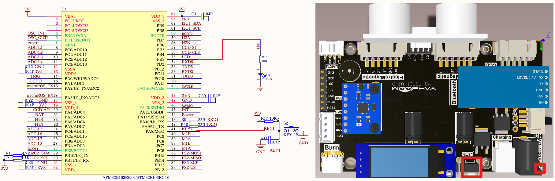
image-20240825210119907

PeripheralsDevelopment boardDescription
LEDPB3The anode of the LED is connected to the development board PB3, and the cathode is connected to the development board GND
KEY1PA8One end of the KEY is connected to the PA8 pin, and the other end is connected to GND

Control principle

By using a button to reset the count value of the independent watchdog (IWDG), the dog feeding function is realized and the LED is lit.

  • Watchdog

The STM32F103ZET6 has two built-in watchdogs (independent watchdog and window watchdog), which are mainly used for system fault detection and recovery.

WatchdogFunction
Independent WatchdogUsed to detect whether the system is running normally
Window WatchdogUsed to detect system failure
  • Independent Watchdog

The independent watchdog (IWDG) is driven by a dedicated low-speed clock (LSI), and it is still effective even if the main clock fails;

When the system does not feed the dog (reset the count value) within a certain period of time, the independent watchdog will trigger a reset operation to restart the system.

xxxxxxxxxx
The main function of the independent watchdog is to prevent the system from entering a dead loop or infinite delay during operation, and to avoid the system from being unresponsive or freezing for a long time.
  • Independent watchdog features

  • Free-running down counter

  • After the watchdog is activated, a reset is generated when the counter counts to 0x000

  • The clock is provided by an independent RC oscillator (can work in stop and standby modes)
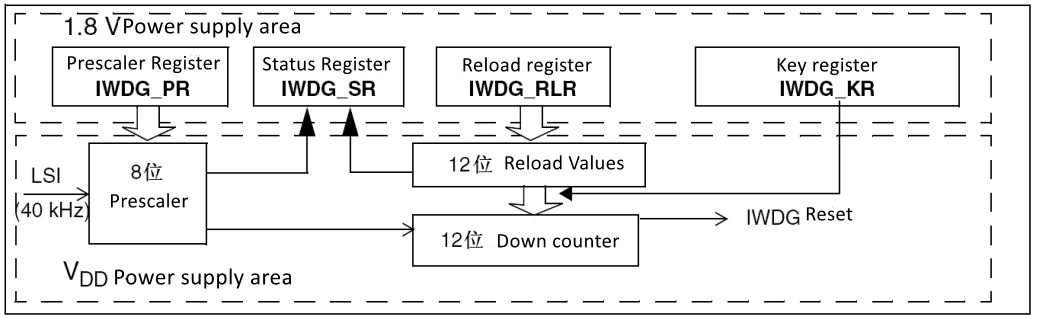
image-20231030220806595

  • Watchdog timeout: 40kHz input clock (LSI)

PrescalerPR[2:0]Minimum time (ms): RL[11:0]=0x000Maximum time (ms): RL[11:0]=0xFFF
/400.1409.6
/810.2819.2
/1620.41638.4
/3430.83276.8
/6441.66553.6
/12853.213107.2
/2566 or 76.426214.4
xxxxxxxxxx
The pre-scaling coefficient set in the tutorial is 256, and the reload value is 156
TTimeout(s)=4∗2PR∗ReloadLSI=256∗15640000≈1s

Software Configuration

Software Code

Configure the timeout reset function of the independent watchdog (IWDG), without configuring specific pins.

xxxxxxxxxx
Product supporting materials source code path: Attachment → Source Code Summary → 1.Base_Course → 12.IWDG

Control Function

The tutorial only briefly introduces the code, and you can open the project source code for details.

IWDG_Start

xxxxxxxxxx
void IWDG_Start(void)
{
    IWDG_WriteAccessCmd(IWDG_WriteAccess_Enable);
    IWDG_SetPrescaler(IWDG_Prescaler_256);
    IWDG_SetReload(155); //1s ≈ (1/40000)*256*(155+1) Watchdog feeding time is set within 1s
    IWDG_Enable();
    IWDG_ReloadCounter();
}

Experimental phenomenon

The IWDG.hex file generated by the project compilation is located in the OBJ folder of the IWDG project. Find the IWDG.hex file corresponding to the project and use the FlyMcu software to download the program into the development board.

After the program is downloaded successfully: press KEY1 to feed the dog, the LED lights up; if you do not press KEY, the LED goes out, and the serial port keeps printing start!

When using the serial port debugging assistant, you need to pay attention to the serial port settings. If the settings are wrong, the phenomenon may be inconsistent
SPI communication(SPI)-2.4G handle
Window Watchdog (WWDG)

COMPANY

  • About us
  • Team Style
  • Blog

LEARNING & EXPLORATION

  • Tutorials
  • Edge AI hardware
  • Educational robots
  • Embedded intelligent hardware

WHERE TO BUY

  • Yahboom Online Store
  • Amazon
  • Alibaba
  • AliExpress
  • Mercado

TECHNOLOGY SUPPORT

  • Email: support@yahboom.com

BE A DISTRIBUTOR

  • Email: sales@yahboom.com
QR Code

Copyright © 2017-2026 Yahboom. All Rights Reserved.

EN/中文