Welcome to Self-balancing Robot Car repository
10.K210-Self learning
K210-Self learning
K210-Self learningHardware connectionControl principleMain codeProgram flow chartExperimental phenomenon
The tutorial mainly demonstrates the balance car combined with the K210 vision module for autonomous classification learning and controlling the balance car to specify actions according to classification.
xxxxxxxxxxThe tutorial only introduces the standard library project code
Hardware connection
| Peripherals | Development board |
|---|---|
| K210 vision module: VCC | 5V |
| K210 vision module: TXD | PA2 |
| K210 vision module: RXD | PA3 |
| K210 vision module: GND | GND |
Control principle
Object classification learning is carried out through the K210 vision recognition module, and the learned data is used for object recognition. The classification serial number after object recognition is sent to the development board, and the development board controls the balance car to specify actions according to the serial number.
K210 vision module
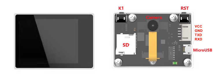
xxxxxxxxxxThe K210 vision module itself is a development board. For detailed usage, please refer to the module supporting tutorial
Download program and model
Download program
Connect the SD card of the K210 vision module to the computer through a card reader, rename the program file to main.py and copy it to the SD card, and then reinstall the SD card into the SD card slot of the K210 vision module.
xxxxxxxxxxThe K210 vision module and development board case code are in the same folder: the folder name will distinguish the development board to which the code belongs
Download model
The model file used by the program needs to be placed in the specified location of the SD card (the sd folder refers to the root directory): /sd/KPU/self_learn_classifier/mb-0.25.kmodel
xxxxxxxxxxProduct supporting materials source code path: Attachment → Source code summary → K210 model filesDirectly unzip the K210 model files and copy the MPU folder inside to the SD card
Sample image
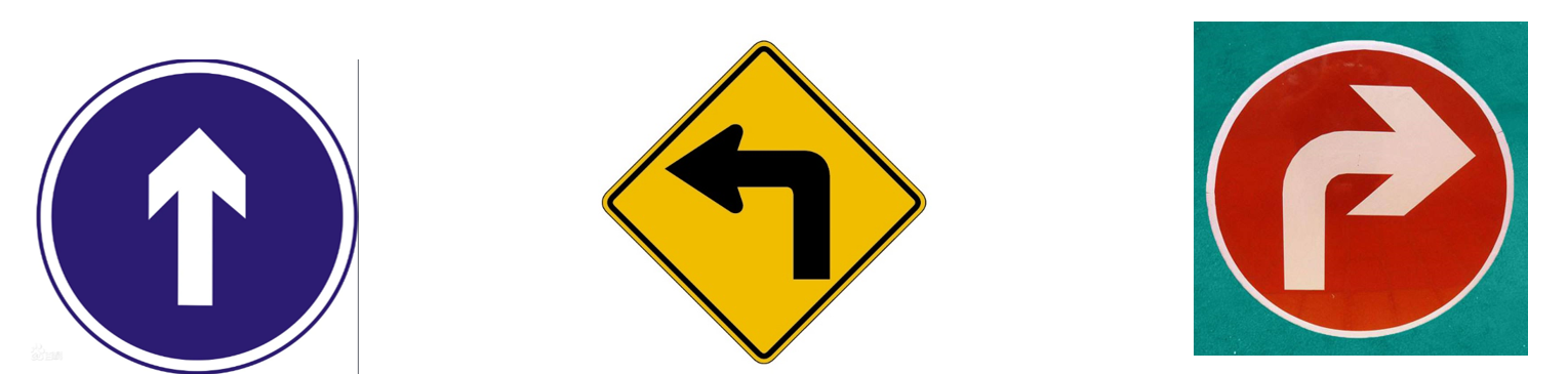
Self-learning
After downloading the program and model to the K210 vision module, the K210 vision module will display Self Learing Demo:
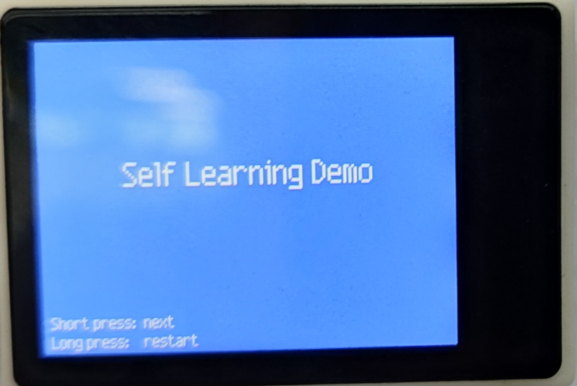
Press the K1 button to enter the next state:
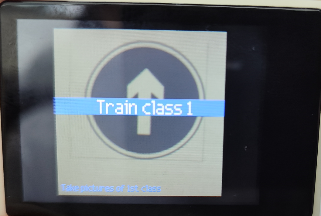
Press the K1 button again to start collecting the image material of the first object. Each object can collect 5 pictures. After collecting, proceed to the next object collection:
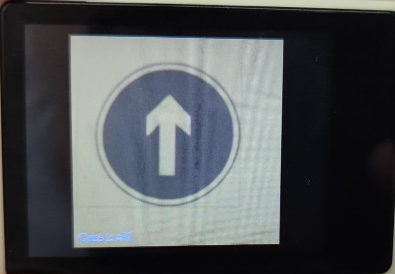
xxxxxxxxxxThe object category and image material number will be prompted in the lower left corner of the screenExample:Class 1: #P1
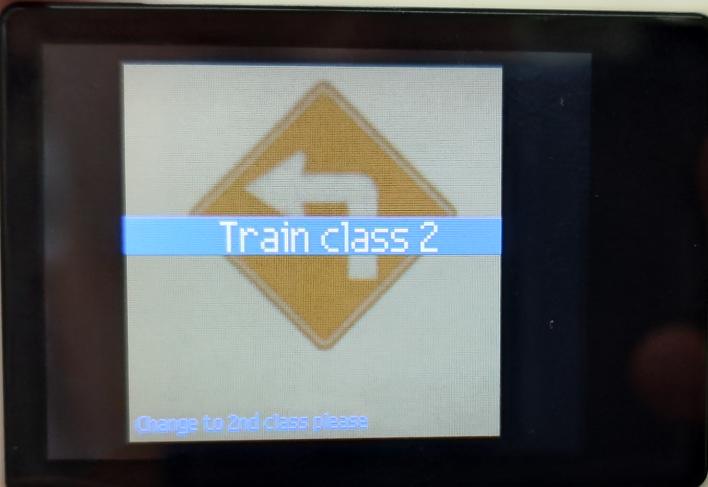
After pressing the K1 button to collect five pictures, enter the next category collection: a total of three categories can be collected, and the collection steps are the same (press the K1 button to confirm the collected category and picture)
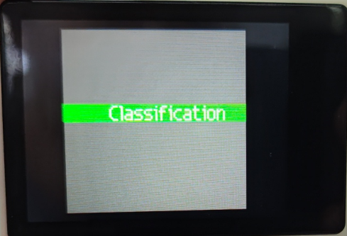
After the collection is completed, the screen displays Classificatiion to indicate that it has entered the classification state. Press the BOOT button again to automatically disappear the prompt.
Recognition effect
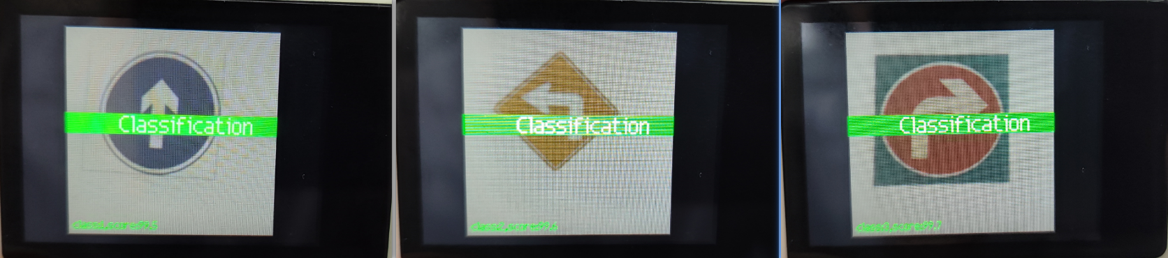
If the recognition effect is not good, or the image acquisition is wrong, you can press reset or press and hold the BOOT button to restart.
Communication protocol
The program of the K210 vision module will automatically recognize the object and send the category to the development board for processing.
| Data header | Data (X represents object category) | Data tail | Example |
|---|---|---|---|
| $ | X | # | $1#: represents object classification number 1 |
| $ | X | # | $2#: represents object classification number 2 |
| $ | X | # | $3#: represents object classification number 3 |
Main code
The tutorial mainly explains the code for the K210 self-learning control of the balance car function. For detailed code, please refer to the corresponding project file.
Deal_K210
Receive valid data sent by K210.
xvoid Deal_K210(uint8_t recv_msg){if (recv_msg == '$' && g_new_flag == 0){g_new_flag = 1;memset(buf_msg, 0, sizeof(buf_msg)); // Clear old datareturn;}if(g_new_flag == 1){if (recv_msg == '#'){g_new_flag = 0;g_index = 0;g_new_data = 1;}if (g_new_flag == 1 && recv_msg != '$'){buf_msg[g_index++] = recv_msg;if(g_index > 20) // Array overflow{g_index = 0;g_new_flag = 0;g_new_data = 0;memset(buf_msg, 0, sizeof(buf_msg)); // Clear old data}}}}
Change_state
根据k210发来的不同指令执行不同的动作。
xxxxxxxxxxvoid Change_state(void){if(g_new_data == 1){g_new_data = 0;if (strcmp("1", buf_msg) == 0 ){// The car moves forward for two seconds and then stopsMove_X = Go_speed;my_delay(2);Move_X = 0;}else if (strcmp("2", buf_msg) == 0){// The car turns left for 1 second and then moves forward for 1 second before stoppingMove_Z = -Trun_speed;my_delay(1);Move_Z = 0;Move_X = Go_speed;my_delay(1);Move_X = 0;}else if (strcmp("3", buf_msg) == 0 ){// The car turns right for 1 second and then moves forward for 1 second before stoppingMove_Z = Trun_speed;my_delay(1);Move_Z = 0;Move_X = Go_speed;my_delay(1);Move_X = 0;}}}
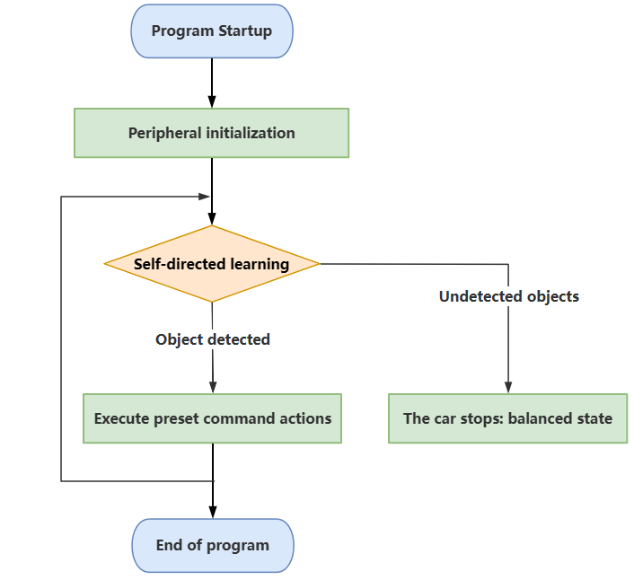
Program flow chart
Briefly introduce the process of function implementation:
Experimental phenomenon
Software code
The K210_BalancedCar_SelfLearn.hex file generated by the project compilation is located in the OBJ folder of the K210_BalancedCar_SelfLearn project. Find the K210_BalancedCar_SelfLearn.hex file corresponding to the project and use the FlyMcu software to download the program to the development board.
xxxxxxxxxxThe corresponding functions can only be realized after both the K210 visual module and the development board have downloaded the programProduct supporting materials source code path: Attachment → Source code summary → 5.Balanced_Car_Extended → 10.K210_BalancedCar_SelfLearn
Experimental phenomenon
Before starting the program, you need to perform self-learning first. After completion, press the KEY1 button according to the OLED prompt to start the self-learning control function of the balance car: OLED displays Start control!; the K210 visual recognition module will perform the corresponding action when it recognizes the object; if no object is recognized, the balance car will remain balanced.
The program has voltage detection. If the voltage is less than 9.6V, the low voltage alarm is triggered and the buzzer will sound.Common situations in which the voltage alarm is triggered:1. The power switch of the development board is not turned on, and only the Type-C data cable is connected for power supply2. The battery pack voltage is lower than 9.6V and needs to be charged in time