Welcome to Self-balancing Robot Car repository
11.SPI communication(SPI)-2.4G handle
SPI communication (SPI)
SPI communication (SPI)Hardware connectionControl PrincipleSoftware configurationPin definitionSoftware codeControl functionExperimental phenomenon
The tutorial demonstrates how to use SPI to read the key values of a 2.4G wireless controller and print them through the serial port.
The tutorial only introduces the standard library project code
Hardware connection
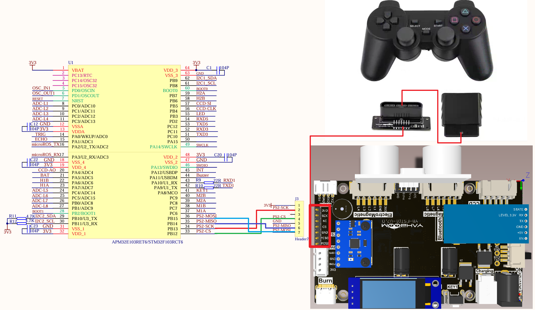
Since we have configured a special connection line, we only need to install it to the corresponding interface:
| Peripherals | Development Board |
|---|---|
| PS2: CS | PB12 |
| PS2: SCK | PB13 |
| PS2: MISO | PB14 |
| PS2: MOSI | PB15 |
Control Principle
SPI (Serial Peripheral Interface) is a high-speed, full-duplex, synchronous serial communication interface that is commonly used to transmit data between microcontrollers, sensors, and external devices.
| SPI Pin | Function |
|---|---|
| MISO | Master data output line, sends data from the master to the slave |
| MOSI | Master data input line, transmits data from the slave to the master |
| SCLK | Clock signal line, used for timing control of synchronous data transmission |
| CS | Slave select line, used to select a specific slave device to communicate with the master |
SPI transmission mode
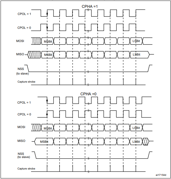
Clock polarity (CPOL): controls the idle and active states of the clock signal (0: idle state low level, 1: idle state high level)
Clock phase (CPHA): controls the sampling and transmission time of data (0: odd transition edge sampling, 1: even transition edge sampling)
| Clock polarity (CPOL) | Clock phase (CPHA) | |
|---|---|---|
| 0 | 0 | SCL idle state low level; data is sampled on the rising edge and transmitted on the falling edge |
| 0 | 1 | SCL idle state low level; data is sampled on the falling edge and transmitted on the rising edge |
| 1 | 0 | SCL idle state high level; data is sampled on the falling edge and transmitted on the rising edge |
| 1 | 1 | SCL idle state high level; data is sampled on the rising edge and transmitted on the falling edge |
2.4G wireless handle
The 2.4G wireless handle is mainly composed of a handle and a receiver (the receiver adapter board is convenient for pin connection with the development board).
Handle
Send key information to the receiver.
Receiver
Receive the data sent by the handle and pass it to the development board; the development board can also send data through the handle to configure the handle's sending mode.

Controller mode description
Single light mode: one controller indicator light is on
Dual light mode: two controller indicator lights are on
Controller Button Description
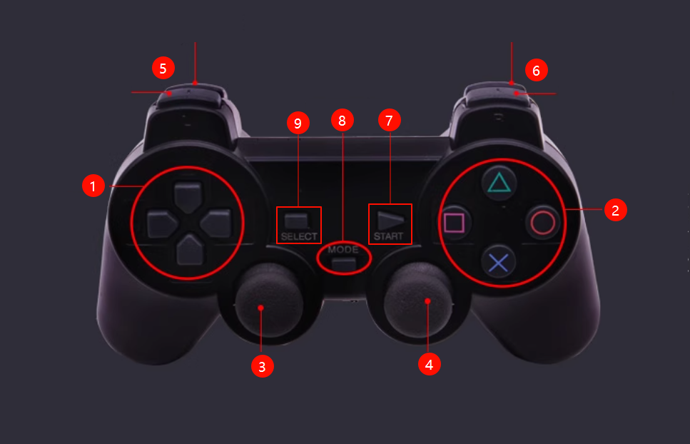
| Controller Button | Program Function Description | Program Definition (Part) |
|---|---|---|
| Direction Key (①): △ | Forward | PSB_PAD_UP |
| Direction Key (①): ▽ | Backward | PSB_PAD_DOWN |
| Direction Key (①): ◁ | Turn Left | PSB_PAD_LEFT |
| Direction Key (①): ▷ | Turn Right | PSB_PAD_RIGHT |
| Function Key (②): ▲ | Forward | PSB_TRIANGLE/PSB_GREEN |
| Function Key (②): × | Backward | PSB_CROSS/PSB_BLUE |
| Function key (②): ☐ | Turn left | PSB_SQUARE/PSB_PINK |
| Function key (②): ◯ | Turn right | PSB_CIRCLE/PSB_RED |
| Joystick: ③ | Control direction (valid in dual-light mode) | PSB_L3/PSS_LX/PSS_LY |
| Joystick: ④ | Control direction (valid in dual-light mode) | PSB_R3/PSS_RX/PSS_RY |
| Button (⑤): L1/L2 | Accelerate | PSB_L1/PSB_L2 |
| Button (⑥): R1/R2 | Decelerate | PSB_R1/PSB_R2 |
| Button (⑦): START | Turn off power saving mode | PSB_START |
| Button (⑧): MODE | Switch mode (indicator light display: single light and dual light mode) | |
| Key (⑨): SELECT | Unused | PSB_SELECT |
Receiver and adapter board pin description
| Receiver pin | Description |
|---|---|
| DI/DAT | Signal flow, from handle to host, this signal is an 8-bit serial data, synchronously transmitted on the falling edge of the clock. The signal is read when the clock changes from high to low. |
| DI/DAT | Signal flow, from host to handle, this signal is relative to DI, the signal is an 8-bit serial data, synchronously transmitted on the falling edge of the clock. |
| NC | Empty port. |
| GND | Receiver working power supply, power supply range 3~5V. |
| VDD | Used to provide handle trigger signal. During communication, it is at low level. |
| CS/SEL | Signal flow, from host to handle, this signal is relative to DI, the signal is an 8-bit serial data, synchronously transmitted on the falling edge of the clock. |
| CS/SEL | Clock signal, sent by the host, used to keep data synchronized. |
| NC | Empty port. |
| ACK | Acknowledgement signal from the controller to the host. This signal goes low at the last cycle of each 8-bit data transmission and CS remains low. If the CS signal does not go low, the PS host will try another peripheral in about 60 microseconds. The ACK port is not used during programming. (Can be ignored) |

Software configuration
Pin definition
| Main control chip | Pin | Main function (after reset) | Default multiplexing function | Redefine function |
|---|---|---|---|---|
| STM32F103RCT6 | PB12 | PB12 | SPI2_NSS/I2C2_SMBAI/USART3_CK/TIM1_BKIN | |
| STM32F103RCT6 | PB13 | PB13 | SPI2_SCK/USART3_CTS/ TIM1_CH1N | |
| STM32F103RCT6 | PB14 | PB14 | SPI2_MISO/USART3_RTS/TIM1_CH2N | |
| STM32F103RCT6 | PB15 | PB15 | SPI2_MOSI/TIM1_CH3N |
Software code
Since the default function of the pin is the ordinary IO pin function, we need to use the multiplexing function.
xxxxxxxxxxProduct supporting materials source code path: Attachment → Source code summary → 1.Base_Course → 11.SPI
Control function
The tutorial only briefly introduces the code, you can open the project source code to read it in detail.
PS2_Init
xvoid PS2_Init(void){GPIO_InitTypeDef GPIO_InitStructure; //Define GPIO_InitStructure structure//DIRCC_APB2PeriphClockCmd(PS_RCC_DI,ENABLE);GPIO_InitStructure.GPIO_Mode=GPIO_Mode_IPU; //Pull-up, pull-down and floating input modes will cause abnormalities when the handle is not connectedGPIO_InitStructure.GPIO_Pin=PS_PIN_DI;GPIO_InitStructure.GPIO_Speed=GPIO_Speed_50MHz; //50MHZGPIO_Init(PS_PORT_DI,&GPIO_InitStructure);//DORCC_APB2PeriphClockCmd(PS_RCC_DO,ENABLE); //Turn on GPIOB clockGPIO_InitStructure.GPIO_Mode=GPIO_Mode_Out_PP; //Multiplexed push-pull output modeGPIO_InitStructure.GPIO_Pin=PS_PIN_DO; //DO portGPIO_InitStructure.GPIO_Speed=GPIO_Speed_50MHz; //50MHZGPIO_Init(PS_PORT_DO,&GPIO_InitStructure);//CSRCC_APB2PeriphClockCmd(PS_RCC_CS,ENABLE); //Turn on GPIOB clockGPIO_InitStructure.GPIO_Mode=GPIO_Mode_Out_PP; //Multiplexed push-pull output modeGPIO_InitStructure.GPIO_Pin=PS_PIN_CS; //CS portGPIO_InitStructure.GPIO_Speed=GPIO_Speed_50MHz; //50MHZGPIO_Init(PS_PORT_CS,&GPIO_InitStructure);//SCKRCC_APB2PeriphClockCmd(PS_RCC_CLK,ENABLE); //Turn on GPIOB clockGPIO_InitStructure.GPIO_Mode=GPIO_Mode_Out_PP; //Multiplexed push-pull output modeGPIO_InitStructure.GPIO_Pin=PS_PIN_CLK; //CLK portGPIO_InitStructure.GPIO_Speed=GPIO_Speed_50MHz; //50MHZGPIO_Init(PS_PORT_CLK,&GPIO_InitStructure);}
PS2_Cmd
xxxxxxxxxxvoid PS2_Cmd(u8 CMD){}
PS2_RedLight
xxxxxxxxxxu8 PS2_RedLight(void){volatile u16 ref=0x01;Data[1] = 0;for(ref=0x01;ref<0x0100;ref<<=1){if(ref&CMD){DO_H; //output a control bit}else DO_L;CLK_H; //clock highDELAY_TIME;CLK_L;DELAY_TIME;CLK_H;if(DI) //when highData[1] = ref|Data[1];}delay_us(16);}
PS2_ReadData
xxxxxxxxxxvoid PS2_ReadData(void){volatile u8 byte=0;volatile u16 ref=0x01;CS_L;PS2_Cmd(Comd[0]);PS2_Cmd(Comd[1]);for(byte=2;byte<9;byte++){for(ref=0x01;ref<0x100;ref<<=1){CLK_H;DELAY_TIME;CLK_L;DELAY_TIME;CLK_H;if(DI)Data[byte] = ref|Data[byte];}delay_us(16);}CS_H;}
PS2_DataKey
xxxxxxxxxxu8 PS2_DataKey(){u8 index;PS2_ClearData();PS2_ReadData();Handkey=(Data[4]<<8)|Data[3];for(index=0;index<16;index++){if((Handkey&(1<<(MASK[index]-1)))==0)return index+1;}return 0;}
PS2_AnologData
xxxxxxxxxxu8 PS2_AnologData(u8 button){return Data[button];}
PS2_ClearData
xxxxxxxxxxvoid PS2_ClearData(){u8 a;for(a=0;a<9;a++)Data[a]=0x00;}
PS2_Vibration
xxxxxxxxxxvoid PS2_Vibration(u8 motor1, u8 motor2){CS_L;delay_us(16);PS2_Cmd(0x01);PS2_Cmd(0x42);PS2_Cmd(0X00);PS2_Cmd(motor1);PS2_Cmd(motor2);PS2_Cmd(0X00);PS2_Cmd(0X00);PS2_Cmd(0X00);PS2_Cmd(0X00);CS_H;delay_us(16);}
PS2_ShortPoll
xxxxxxxxxxvoid PS2_ShortPoll(void){CS_L;delay_us(16);PS2_Cmd(0x01);PS2_Cmd(0x42);PS2_Cmd(0X00);PS2_Cmd(0x00);PS2_Cmd(0x00);CS_H;delay_us(16);}
PS2_EnterConfing
xxxxxxxxxxvoid PS2_EnterConfing(void){CS_L;delay_us(16);PS2_Cmd(0x01);PS2_Cmd(0x43);PS2_Cmd(0X00);PS2_Cmd(0x01);PS2_Cmd(0x00);PS2_Cmd(0X00);PS2_Cmd(0X00);PS2_Cmd(0X00);PS2_Cmd(0X00);CS_H;delay_us(16);}
PS2_TurnOnAnalogMode
xxxxxxxxxxvoid PS2_TurnOnAnalogMode(void){CS_L;PS2_Cmd(0x01);PS2_Cmd(0x44);PS2_Cmd(0X00);PS2_Cmd(0x01);PS2_Cmd(0xEE);PS2_Cmd(0X00);PS2_Cmd(0X00);PS2_Cmd(0X00);PS2_Cmd(0X00);CS_H;delay_us(16);}
PS2_VibrationMode
xxxxxxxxxxvoid PS2_VibrationMode(void){CS_L;delay_us(16);PS2_Cmd(0x01);PS2_Cmd(0x4D);PS2_Cmd(0X00);PS2_Cmd(0x00);PS2_Cmd(0X01);CS_H;delay_us(16);}
PS2_ExitConfing
xxxxxxxxxxvoid PS2_ExitConfing(void){CS_L;delay_us(16);PS2_Cmd(0x01);PS2_Cmd(0x43);PS2_Cmd(0X00);PS2_Cmd(0x00);PS2_Cmd(0x5A);PS2_Cmd(0x5A);PS2_Cmd(0x5A);PS2_Cmd(0x5A);PS2_Cmd(0x5A);CS_H;delay_us(16);}
PS2_SetInit
xxxxxxxxxxvoid PS2_SetInit(void){PS2_ShortPoll();PS2_ShortPoll();PS2_ShortPoll();PS2_EnterConfing(); //Enter configuration modePS2_TurnOnAnalogMode(); //"Traffic light" configuration mode, and choose whether to save//PS2_VibrationMode(); //Turn on vibration modePS2_ExitConfing(); //Complete and save configuration}
Experimental phenomenon
The SPI.hex file generated by the project compilation is located in the OBJ folder of the SPI project. Find the SPI.hex file corresponding to the project and use the FlyMcu software to download the program to the development board.
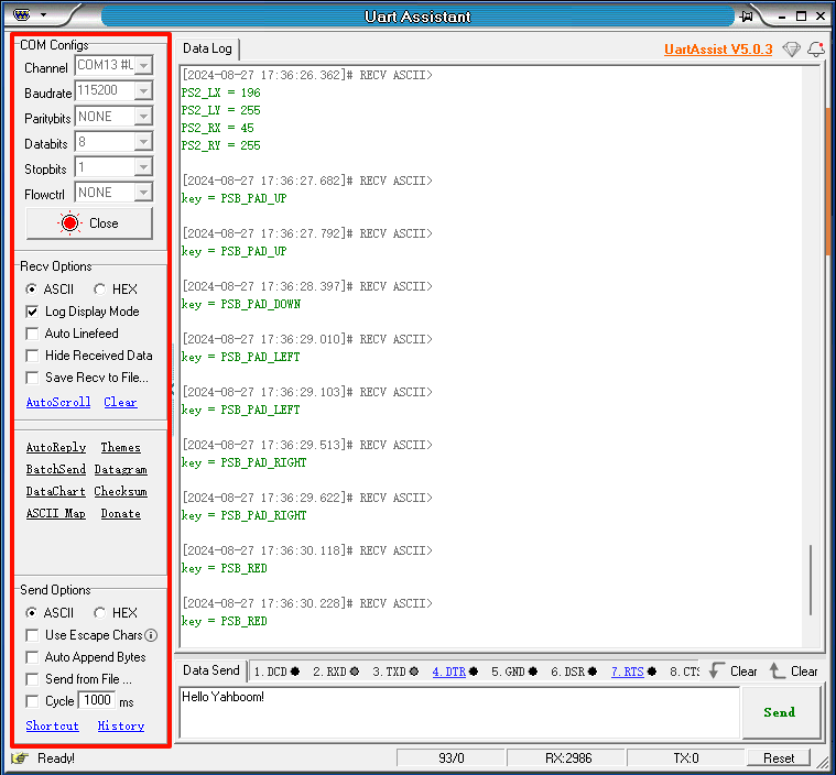
After the program is successfully downloaded: the serial port prints the key value pressed by the wireless controller.
xxxxxxxxxxWhen using the serial port debugging assistant, you need to pay attention to the serial port settings. If the settings are wrong, the phenomenon may be inconsistent.