Welcome to Self-balancing Robot Car repository
11.K210 module-Serial communication (USART)
K210 module-Serial communication (USART)
K210 module-Serial communication (USART)Hardware connectionControl principleSoftware configurationPin definitionSoftware codeControl functionExperimental phenomenon
The tutorial controls the RGB light color of the K210 visual module through buttons.
The tutorial only introduces the standard library project code
Hardware connection
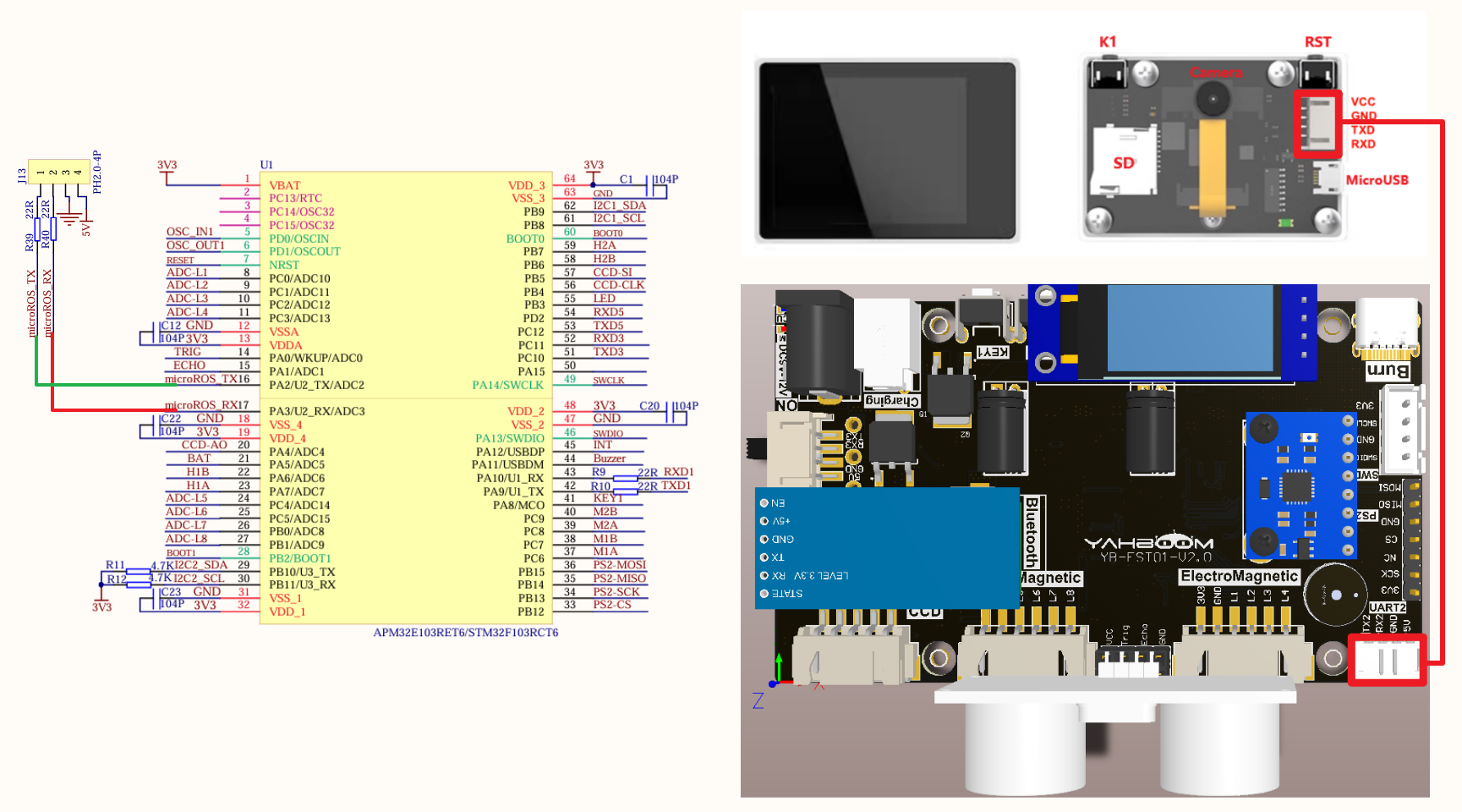
Since we have configured a special connection line, we only need to install it to the corresponding interface:
| Peripherals | Development board |
|---|---|
| K210 visual module: VCC | 5V |
| K210 visual module: TXD | PA2 |
| K210 visual module: RXD | PA3 |
| K210 visual module: GND | GND |
Control principle
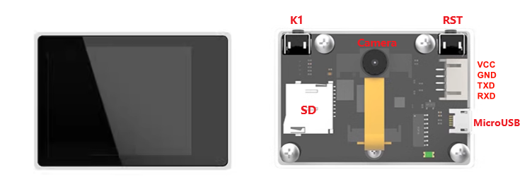
K210 visual module
The K210 visual module itself is a development board. For detailed use, please refer to the module supporting tutorial.
Download program
Connect the SD card of the K210 visual module to the computer through a card reader, rename the program file to main.py and copy it to the SD card, then reinstall the SD card into the SD card slot of the K210 visual module.
xxxxxxxxxxThe K210 visual module and development board case codes are in the same folder: the folder name will distinguish the development board to which the code belongs
Communication protocol
The development board program controls serial port 2 to send different data through the onboard KEY button;
The K210 visual module program will parse the data sent by the development board serial port 2 and control the color of the RGB light on the K210 visual module board according to the data.
| Number of key presses | Content sent by serial port 2 | K210 visual module RGB light status |
|---|---|---|
| 0 | $blue# | Blue |
| 1 | $red# | Red |
| 2 | $green# | Green |
| 3 | $yellow# | Yellow |
| 4 | $purper# | Purple |
| 5 | $lake# | Cyan |
| 6 | $close# | Close |
Software configuration
Pin definition
| Main control chip | Pin | Main function (after reset) | Default multiplexing function | Redefine function |
|---|---|---|---|---|
| STM32F103RCT6 | PA2 | PA2 | USART2_RTS/ADC123_IN1/TIM5_CH2/TIM2_CH2 | |
| STM32F103RCT6 | PA3 | PA3 | USART2_TX/TIM5_CH3 ADC123_IN2/TIM2_CH3 |
Software code
Since the default pin function is the normal IO pin function, we need to use the default multiplexing function.
xxxxxxxxxxProduct supporting materials source code path: Attachment → Source code summary → 2.Extended_Course → 11.k210
Control function
The tutorial only briefly introduces the code, you can open the project source code to read it in detail.
USART2_init
xvoid USART2_init(u32 baudrate){GPIO_InitTypeDef GPIO_InitStructure;USART_InitTypeDef USART_InitStructure;NVIC_InitTypeDef NVIC_InitStructure;RCC_APB1PeriphClockCmd(RCC_APB1Periph_USART2, ENABLE);RCC_APB2PeriphClockCmd(RCC_APB2Periph_GPIOA , ENABLE);GPIO_InitStructure.GPIO_Pin = GPIO_Pin_2;GPIO_InitStructure.GPIO_Mode = GPIO_Mode_AF_PP;GPIO_InitStructure.GPIO_Speed = GPIO_Speed_50MHz;GPIO_Init(GPIOA, &GPIO_InitStructure);GPIO_InitStructure.GPIO_Pin = GPIO_Pin_3;GPIO_InitStructure.GPIO_Mode = GPIO_Mode_IN_FLOATING;GPIO_Init(GPIOA, &GPIO_InitStructure);NVIC_InitStructure.NVIC_IRQChannel = USART2_IRQn;NVIC_InitStructure.NVIC_IRQChannelPreemptionPriority = 1;NVIC_InitStructure.NVIC_IRQChannelSubPriority = 1;NVIC_InitStructure.NVIC_IRQChannelCmd = ENABLE;NVIC_Init(&NVIC_InitStructure);USART_InitStructure.USART_BaudRate = baudrate;USART_InitStructure.USART_WordLength = USART_WordLength_8b;USART_InitStructure.USART_StopBits = USART_StopBits_1;USART_InitStructure.USART_Parity = USART_Parity_No ;USART_InitStructure.USART_HardwareFlowControl = USART_HardwareFlowControl_None;USART_InitStructure.USART_Mode = USART_Mode_Rx | USART_Mode_Tx;USART_Init(USART2, &USART_InitStructure);USART_ITConfig(USART2, USART_IT_RXNE, ENABLE);//USART_ClearFlag(USART2,USART_FLAG_TC);USART_Cmd(USART2, ENABLE);}
USART2_Send_U8
xxxxxxxxxxvoid USART2_Send_U8(uint8_t ch){while (USART_GetFlagStatus(USART2, USART_FLAG_TXE) == RESET);USART_SendData(USART2, ch);}
USART2_Send_ArrayU8
xxxxxxxxxxvoid USART2_Send_ArrayU8(uint8_t *BufferPtr, uint16_t Length){while (Length--){USART2_Send_U8(*BufferPtr);BufferPtr++;}}
USART2_IRQHandler
xxxxxxxxxxvoid USART2_IRQHandler(void){uint8_t Rx2_Temp;if (USART_GetITStatus(USART2, USART_IT_RXNE) != RESET){USART_ClearITPendingBit(USART2, USART_IT_RXNE);Rx2_Temp = USART_ReceiveData(USART2);Deal_K210(Rx2_Temp);}}
Experimental phenomenon
The K210.hex file generated by the project compilation is located in the OBJ folder of the K210 project. Find the K210.hex file corresponding to the project and use the FlyMcu software to download the program to the development board.
xxxxxxxxxxThe corresponding functions can only be realized when both the K210 visual module and the development board have downloaded the program
After the program is successfully downloaded: press the KEY button to switch the RGB light color of the K210 visual module.