Welcome to Self-balancing Robot Car repository
Autonomous Driving
18.Autonomous Driving
18.Autonomous DrivingRequirementsChannel TrackingHardware connectionControl principleMPU6050 Yaw Angle DiagramSolution Approach and Reference CodeProblem 1Problem 2Problem 3&4
Requirements
Task Design an autonomous driving car controlled by a TI MSPM0 series MCU that can navigate a specified path automatically. The area of operation should be as illustrated in Figure 1, with a minimum size of 220 cm × 120 cm. The two symmetrical semicircular arcs in the diagram have a radius of 40 cm, and the arcs are black with a width of approximately 1.8 cm. The four vertices of the arcs are designated as points A, B, C, and D. It is recommended to use white matte spray-painted fabric for the area. No additional markings are allowed in the area apart from the two semicircles.
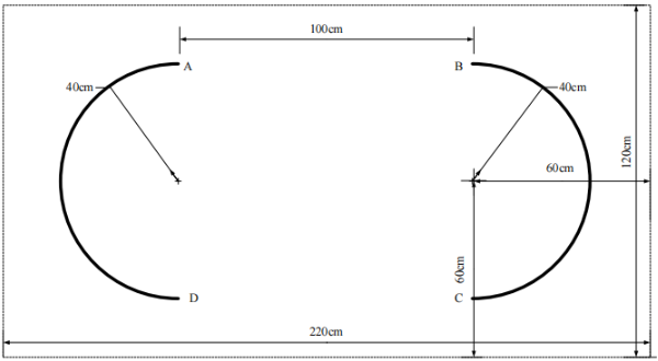
Requirements (1) Place the car at point A. The car should autonomously travel to point B and stop there, providing audio-visual alerts upon stopping. The time taken should not exceed 15 seconds. (20 points)
(2) Place the car at point A. The car should travel to point B, then proceed along the semicircular arc to point C, then automatically move from point C to point D, and finally return along the semicircular arc to point A and stop. An audio-visual alert should be given at each point. The total time for completing this circuit should not exceed 30 seconds. (20 points)
(3) Place the car at point A. The car should travel to point C, then proceed along the semicircular arc to point B, then automatically move from B to D, and finally return along the semicircular arc to point A and stop. An audio-visual alert should be given at each point. The total time for completing this circuit should not exceed 40 seconds. (30 points)
(4) The car should automatically perform the route as described in requirement 3 for 4 complete circuits, with the goal of minimizing the time taken. (30 points)
(5) Design report. (20 points)
link
https://res.nuedc-training.com.cn/topic/2024/topic_116.html
Channel Tracking
Hardware connection
| LED corresponding to the four-way patrol module | Four-way patrol module | Development board |
|---|---|---|
| VCC | 5V/3.3V | |
| L1 | X1 | PC4 |
| L2 | X2 | PC5 |
| L3 | X3 | PB0 |
| L4 | X4 | PB1 |
| GND | GND |
Control principle
By reading the X1, X2, X3, and X4 interface levels of the four-way tracking module, it is determined whether the black line is detected and where the black line is located.
xxxxxxxxxxThe program uses PID to implement the line patrol function. If the PID parameters are not used, the effect is poor.
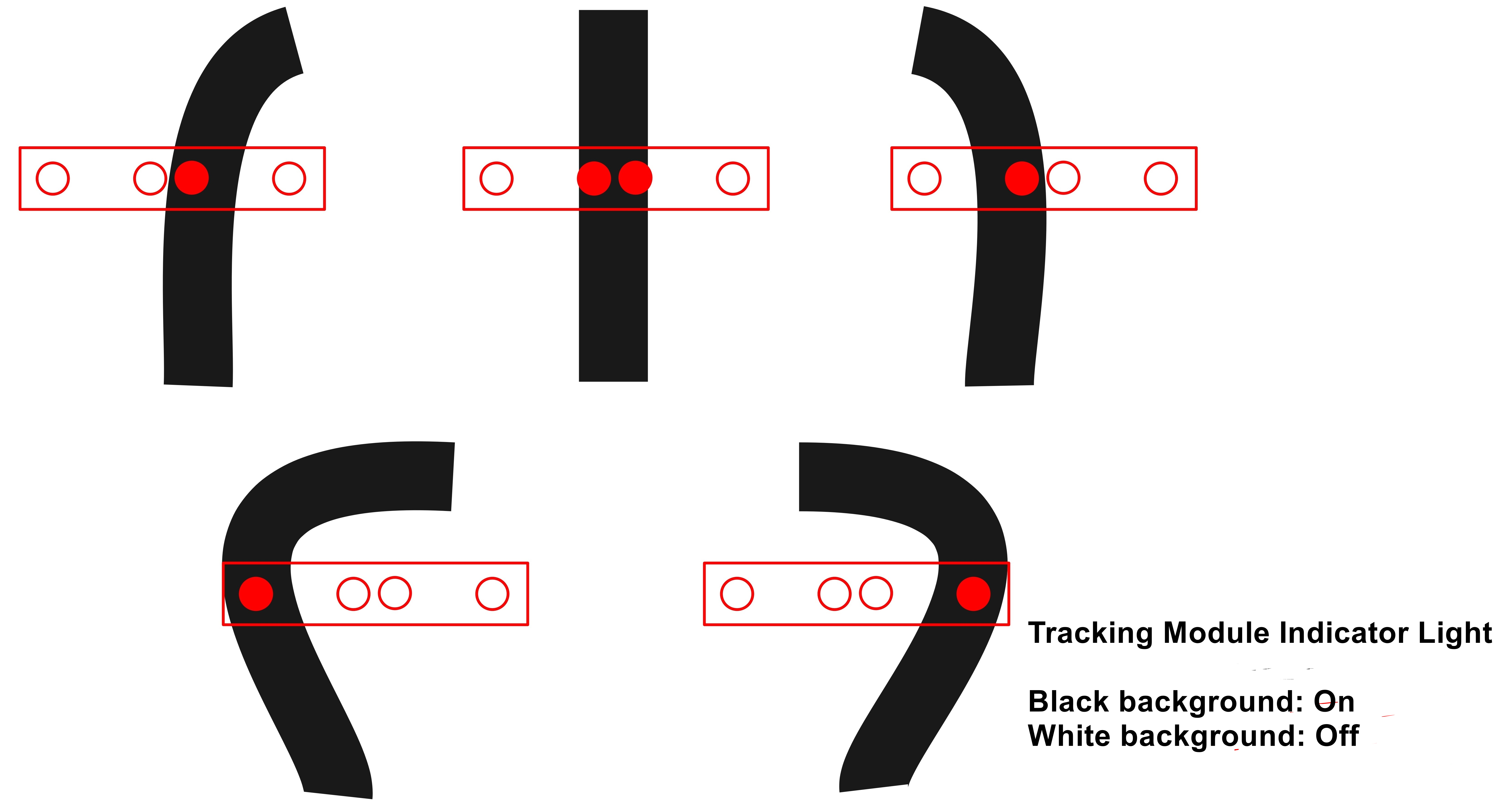
Black line detected
The light is on → The corresponding interface of the four-way line patrol module outputs a low level;
White line detected
The light is off → The corresponding interface of the four-way line patrol module outputs a high level.
xxxxxxxxxx注意:接口、LED、调节旋钮对应关系以丝印数字为准,例如:X1对应L1、SW1
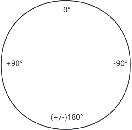
MPU6050 Yaw Angle Diagram
Solution Approach and Reference Code
Problem 1
Issue
Due to factors like motor speed variations and ground friction, applying the same PWM value to both the left and right motors may result in different rotational speeds, causing the car to veer off course.
Solution Approach
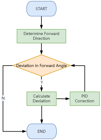
Utilize the MPU6050 sensor to read the car's yaw angle. Implement a PID control loop to adjust the car's heading, ensuring it moves straight.
Flowchart
Reference Code
x // main.c Stop_Flag = 0; sprintf(showbuf,"%d %d %d %d",IN_X2,IN_X1,IN_X3,IN_X4); OLED_Draw_Line(showbuf, 1, true, true); // The time interval for car operation needs to be set based on actual conditions. int timer_count_min = 300; int timer_count_max = 700; if((IN_X1==0 || IN_X3==0 || IN_X2==0 || IN_X4==0 || timer_count>timer_count_max) && timer_count>timer_count_min){ go_front = false; running_mode = RUNNING_MODE_STOP; BEEP_BEEP = 1; delay_time(150); BEEP_BEEP = 0; }
// app_tracking.c // Steering Control Loop PID int Keep_turn_front_PD(float gyro, float direction) {
int KTF_Turn = 0; float err = 0; static float KTF_Integral; // Error caused by the MPU6050, yaw_fix needs to be adjusted according to actual conditions. yaw_fix = -0.4; err = (-1)*getDelta(Yaw + yaw_fix, direction); KTF_Integral += err; KTF_Turn = err*KF_Trun_KP+KF_Trun_KI*KTF_Integral+gyro*KF_Trun_KD; return KTF_Turn; } // Rotation Angle Calculation float getDelta(float now, float target){ float dt = target-now; // The yaw angle range of the MPU6050 is [-180 to 180]. if (dt > 180) dt -= 360; else if (dt < -180) dt += 360;
return dt>=180?(360-dt):(dt<=-180?dt+360:dt);
}Problem 2
Solution Approach
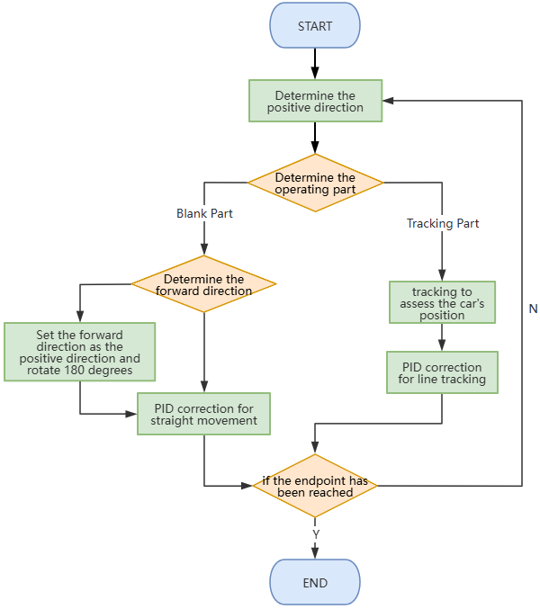
The blank path sections (D->C and B->A) use the solution from the first question, with opposite forward directions set for D->C and B->A. For the tracking part, refer to the car tracking tutorial and adjust the PID values based on actual conditions.
Flowchart
Reference Code
xxxxxxxxxx // Use variable `point_count` to record the number of endpoints, initially set to 1. static int point_count = 1; static int last_in_x1=-1,last_in_x2=-1,last_in_x3=-1,last_in_x4=-1; IRTrack_Trun_KP = 250; // D -> C section: blank; directly adopt the solution from the first question, // with the difference being that `running_mode` is not set to STOP. // C -> B section: line tracking. // B -> A section: blank; reverse `yaw_font`, set `go_front=true`. Stop_Flag = 0; sprintf(showbuf, "Point: %d", point_count); OLED_Draw_Line(showbuf, 2, true, true); if((IN_X1==0 && IN_X3==0 && last_in_x1!=0 && last_in_x3!=0) && timer_count>200){ go_front = false; BEEP_BEEP = 1; delay_time(10); BEEP_BEEP = 0; point_count++; } else if(IN_X1==1 && IN_X3==1 && IN_X2==1 && IN_X4==1 && (last_in_x1==0 || last_in_x3==0) ){ if(point_count == 2){ BEEP_BEEP = 1; delay_time(10); BEEP_BEEP = 0; point_count = 3; // Add a correction for the straight line in the third blank section; // this correction value needs to be adjusted based on actual conditions. float change_dir_fix = -1.55; go_front_dir = change_direction_180(yaw_front)+change_dir_fix; go_front = true; }else if(point_count >= 4){ Stop_Flag = 1; // running_mode == RUNNING_MODE_STOP; BEEP_BEEP = 1; delay_time(50); BEEP_BEEP = 0; delay_time(50); } } // Error correction: if the car does not enter straightly. if((IN_X1==0 || IN_X2==0 || IN_X3==0 || IN_X4==0) && (timer_count - timer_count_recorder[point_count]) > 600){ if(go_front){ go_front = false; BEEP_BEEP = 1; delay_time(100); BEEP_BEEP = 0; point_count++; } } //////////// 结尾部分 ////////////////// last_in_x1 = IN_X1; last_in_x2 = IN_X2; last_in_x3 = IN_X3; last_in_x4 = IN_X4;Problem 3&4
Solution Approach
For the line tracking section, refer to the car tracking tutorial.
To improve accuracy, adjust the PID values in the tracking section based on actual conditions.
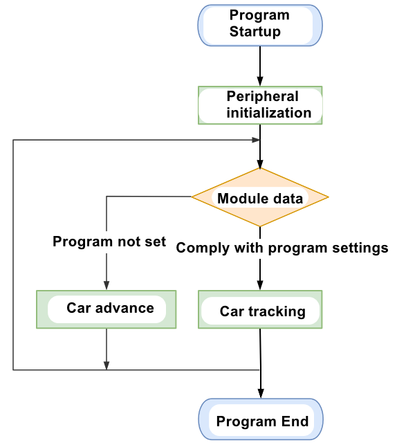
The blank sections need to follow two steps: steady-direction turning and straight movement,
implemented through the steering loop PID from question (1).
xxxxxxxxxxRegarding Errors & Reference Solutions:The MPU6050's Yaw readings have a significant zero-drift issue (approximately 0 to 2 degrees).Reference Solutions:1. Allow the MPU6050 to stabilize after initialization before calibrating the car's positive direction.2. When turning, manually add an inward angle deviation correction value to prevent the car from drifting outward from the tracking path. Inward deviations can be corrected by dynamically adjusting the P parameter values in the PID for the tracking section to keep the car on the track (see detailed code).Different mechanical structures of the car and external environmental factors may cause deviations.Reference Solutions:Monitor the car's operational performance and adjust the offset parameters based on actual running conditions. Specific adjustment locations can be found in the reference code comments.
Flowchart
Reference Code
xxxxxxxxxx    // Use variable point_count to record the number of endpoints, initially set to 0.    static int point_count = 0;    static int last_in_x1=0,last_in_x2=1,last_in_x3=0,last_in_x4=1;    Stop_Flag = 0;    sprintf(showbuf, "go_front_dir:%f ", go_front_dir);    OLED_Draw_Line(showbuf, 1, false, true);
    // Dynamic steering loop Kp, ensuring that the turning speed is low when first entering the line-tracking path.    // To ensure effective line tracking, a relatively large Kp must be maintained during tracking.    // However, a large Kp can cause the car to rotate significantly in the wrong direction if it has an inward deviation before entering the line-tracking path, according to tracking rules.    // Therefore, it is necessary to limit the size of Kp when initially entering the path.    // The specific variation function and parameters need to be adjusted based on actual conditions.    if((IRTrack_Trun_KP < DEFAULT_MAX_KP) && go_front==false){
        // y = 0.018x^{2}        IRTrack_Trun_KP = 0.018*(timer_count - timer_count_recorder[point_count])*(timer_count - timer_count_recorder[point_count]);    }else if(IRTrack_Trun_KP > DEFAULT_MAX_KP){        IRTrack_Trun_KP = DEFAULT_MAX_KP;    }    if(IRTrack_Trun_KP < 0){        IRTrack_Trun_KP = 10;    }

    // The initial state for the third question is that the car is on the line.    // Please set the permissible running time interval according to actual conditions.    if((IN_X1==1 && IN_X3==1 && IN_X2==1 && IN_X4==1            && (last_in_x1==0 || last_in_x3==0))            || (timer_count - timer_count_recorder[point_count]) > 878    ){        if(point_count==0 || (timer_count - timer_count_recorder[point_count]) > 600){            IRTrack_Trun_KP = 75;
    // The error correction offset (fix_degree) and initial deflection angle (base_degree) need to be adjusted based on actual performance.    // Try to bias inward, as inward bias can be corrected, while an outward bias that causes the car to go off the track is difficult to correct.    // Generally, no adjustments are needed during the first lap.            float fix_degree1 = 0;            float fix_degree2 = 0;            float base_degree1 = 35.95;            float base_degree2 = 35;            float val_1 = -4.5;            float val_2 = -2;            if((point_count)%4 == 0){                go_front = false;                if(point_count == 4){                    fix_degree1 = val_1;                }else if(point_count == 8){                    fix_degree1 = val_1;                }else if(point_count == 12){                    fix_degree1 = val_1;                }                go_front_dir = change_direction_any(yaw_front, -(base_degree1 + fix_degree1));                go_front = true;                point_count++;                timer_count_recorder[point_count] = timer_count;                BEEP_BEEP = 1;                delay_time(30);                BEEP_BEEP = 0;            }else if((point_count >= 2 && (point_count - 2) % 4 == 0)){                 go_front = false;                if(point_count == 6){                    fix_degree2 = val_2;                }else if(point_count == 10){                    fix_degree2 = val_2;                }else if(point_count == 14){                    fix_degree2 = val_2;                }                go_front_dir = change_direction_any(change_direction_180(yaw_front),(base_degree2 + fix_degree2));                go_front = true;                point_count++;                timer_count_recorder[point_count] = timer_count;                BEEP_BEEP = 1;                delay_time(30);                BEEP_BEEP = 0;            }
            sprintf(showbuf2, "%.2f  %.2f %d", fix_degree1, fix_degree2, (point_count-1)%4);            OLED_Draw_Line(showbuf2, 3, false, true);        }
    }else if(((last_in_x1==1 && last_in_x2==1 && last_in_x3==1 && last_in_x4==1)             && (IN_X1 == 0 || IN_X2==0 || IN_X3==0 || IN_X4==0))            || timer_count - timer_count_recorder[point_count] > 900    ){        if(point_count==0 || timer_count - timer_count_recorder[point_count] > 700){            if((point_count % 2 != 0) && (point_count > 0)){                // Second segment: tracking.                go_front = false;                point_count++;                timer_count_recorder[point_count] = timer_count;                // IRTrack_Trun_KP = 150;                IRTrack_Trun_KP = 75;                BEEP_BEEP = 1;                delay_time(15);                BEEP_BEEP = 0;            }        }    }
    // Stop    if(point_count >= 17){        Stop_Flag = 1;        // running_mode == RUNNING_MODE_STOP;        BEEP_BEEP = 1;        delay_time(50);        BEEP_BEEP = 0;        delay_time(50);        BEEP_BEEP = 1;        delay_time(50);        BEEP_BEEP = 0;        return 0;    }
    //////////// End //////////////////    last_in_x1 = IN_X1;    last_in_x2 = IN_X2;    last_in_x3 = IN_X3;    last_in_x4 = IN_X4;}
Notes:
- Question (4) has high precision requirements. Please tune the accuracy of the four-channel line tracking module as much as possible to ensure that the balance car can read the correct values when tilting during self-balancing.
- Modifying the OLED-related sections of the code may lead to changes in movement behavior because the OLED output speed is slower, causing a certain delay in the code.
- During operation, please ensure the car is connected to the OLED screen. Tests have shown that if the hardware is not connected during OLED output, the program will lag severely, leading to unstable movement of the car.
- The MPU6050 may, in rare cases, fail to initialize, resulting in readings consistently being 0. Power cycling and leaving it off for about five minutes generally resolves the issue.