Welcome to Self-balancing Robot Car repository
08.Tracking module-Read status (GPIO)
Four-way tracking module:Read status (GPIO)
Four-way tracking module:Read status (GPIO)Hardware connectionControl principleSoftware ConfigurationPin DefinitionSoftware codeControl functionExperimental phenomenon
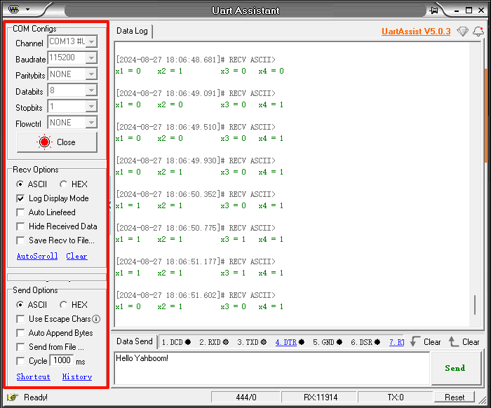
The tutorial demonstrates the serial port and OLED display of the status of each indicator light of the four-way line patrol module.
The tutorial only introduces the standard library project code
Hardware connection
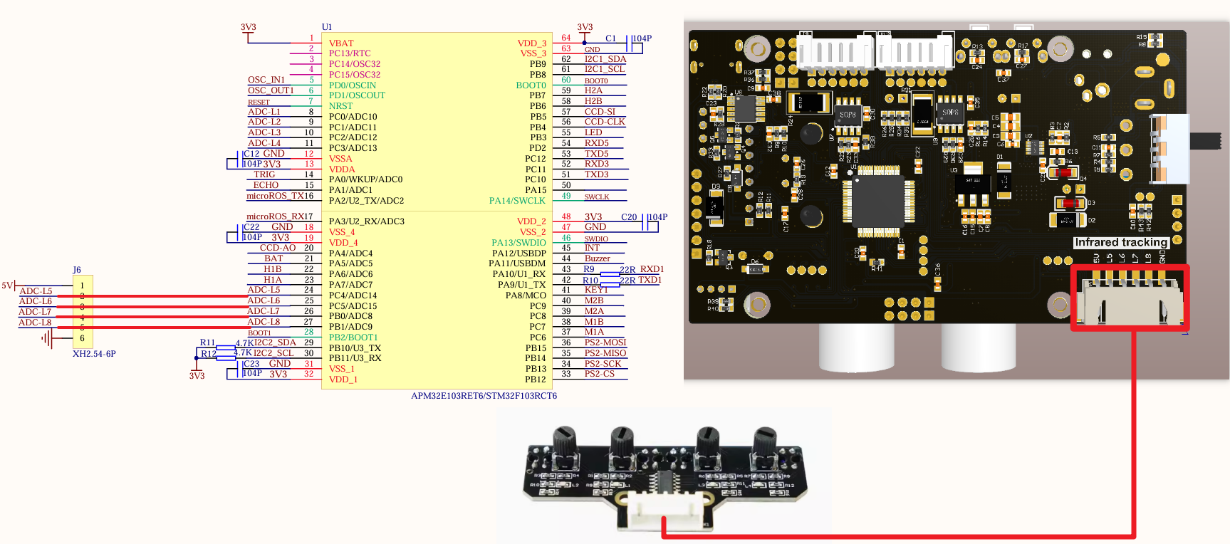
Since we have configured a special connection line, we only need to install it to the corresponding interface:
| Four-way line patrol module corresponding LED | Four-way line patrol module | Development board |
|---|---|---|
| VCC | 5V/3.3V | |
| L1 | X1 | PC4 |
| L2 | X2 | PC5 |
| L3 | X3 | PB0 |
| L4 | X4 | PB1 |
| GND | GND |
Control principle
By reading the X1, X2, X3, and X4 interface levels of the four-way tracking module, it is determined whether the black line is detected and where the black line is located.
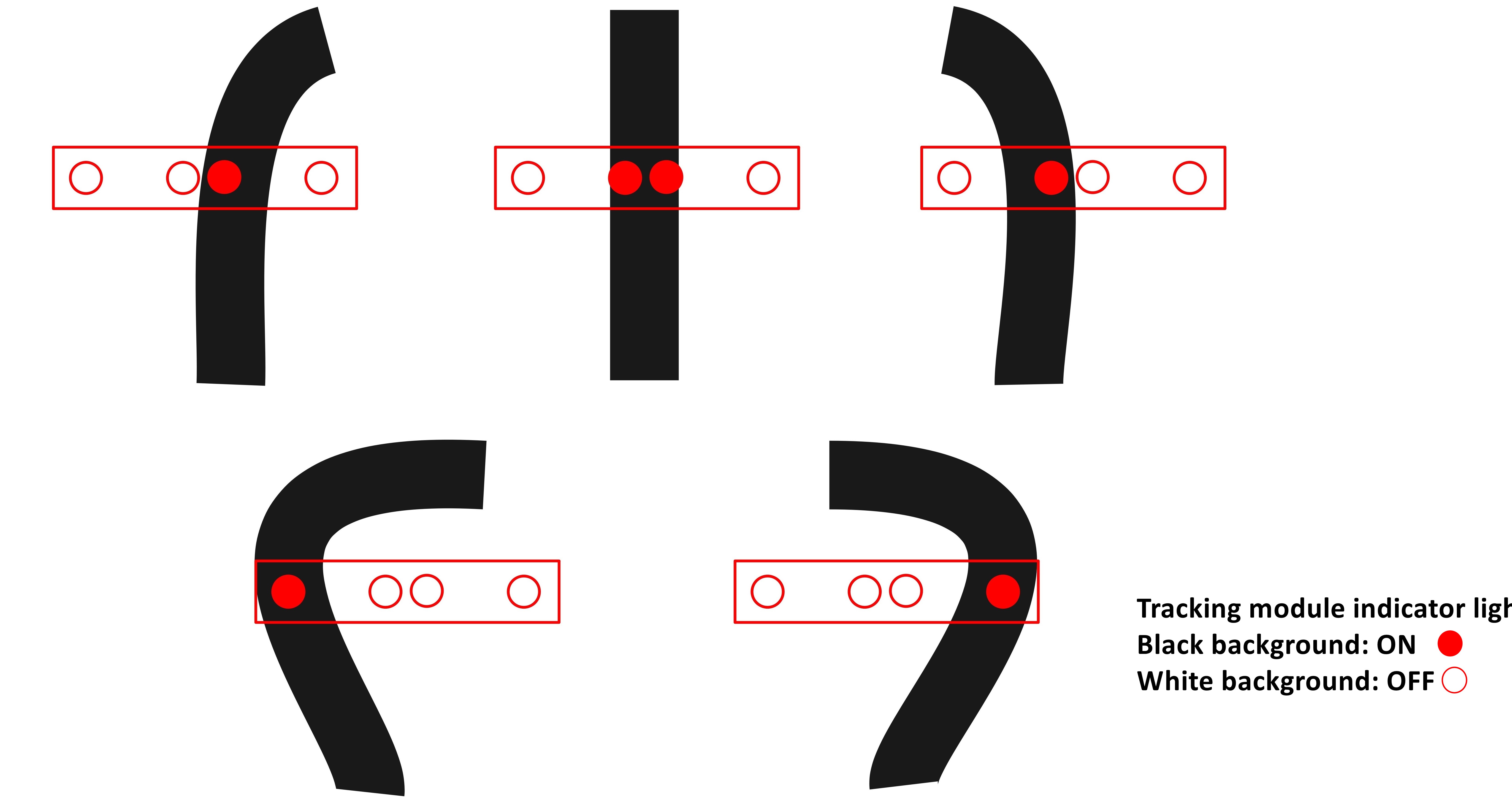
Black line detected
Light on → The corresponding interface of the four-way patrol module outputs a low level;
White line detected
Light off → The corresponding interface of the four-way patrol module outputs a high level.
xxxxxxxxxxNote: The correspondence between the interface, LED, and adjustment knob shall be based on the silk-screen numbers, for example: X1 corresponds to L1, SW1
Software Configuration
Pin Definition
| Main Control Chip | Pin | Main Function (After Reset) | Default Multiplexing Function | Redefine Function |
|---|---|---|---|---|
| STM32F103RCT6 | PC4 | PC4 | ADC12_IN14 | |
| STM32F103RCT6 | PC5 | PC5 | ADC12_IN15 | |
| STM32F103RCT6 | PB0 | PB0 | ADC12_IN8/TIM3_CH3/TIM8_CH2N | TIM1_CH2N |
| STM32F103RCT6 | PB1 | PB1 | ADC12_IN9/TIM3_CH4/TIM8_CH3N | TIM1_CH3N |
Software code
Since the default function of the pin is the normal IO pin function, we need to use the default multiplexing function.
xxxxxxxxxxProduct supporting materials source code path: Attachment → Source code summary → 2.Extended_Course → 8.IRtracking
Control function
The tutorial only briefly introduces the code, you can open the project source code to read it in detail.
irtracking_init
xvoid irtracking_init(void){GPIO_InitTypeDef GPIO_InitStructure;RCC_APB2PeriphClockCmd(IR_X1_Clk|IR_X2_Clk|IR_X3_Clk|IR_X4_Clk, ENABLE);GPIO_InitStructure.GPIO_Mode=GPIO_Mode_IN_FLOATING;GPIO_InitStructure.GPIO_Pin=IR_X1_Pin;GPIO_Init(IR_X1_Port,&GPIO_InitStructure);GPIO_InitStructure.GPIO_Mode=GPIO_Mode_IN_FLOATING;GPIO_InitStructure.GPIO_Pin=IR_X2_Pin;GPIO_Init(IR_X2_Port,&GPIO_InitStructure);GPIO_InitStructure.GPIO_Mode=GPIO_Mode_IN_FLOATING;GPIO_InitStructure.GPIO_Pin=IR_X3_Pin;GPIO_Init(IR_X3_Port,&GPIO_InitStructure);GPIO_InitStructure.GPIO_Mode=GPIO_Mode_IN_FLOATING;GPIO_InitStructure.GPIO_Pin=IR_X4_Pin;GPIO_Init(IR_X4_Port,&GPIO_InitStructure);}
Experimental phenomenon
The IRtracking.hex file generated by the project compilation is located in the OBJ folder of the IRtracking project. Find the IRtracking.hex file corresponding to the project and use the FlyMcu software to download the program to the development board.
After the program is successfully downloaded: the serial port prints and the OLED displays the X1, X2, X3, and X4 interface levels of the four-way tracking module.