yahboom
HomeLearn
Solution
Blog
Online Store
About Us
EN/中文
Self-balancing Robot Car📖
00.Get started quickly
  • 01.Balance car manual
  • 02.Balancing car assembly
  • 03.Get started quickly
  • 04.Balance car interface description
  • 05.Common Problem Analysis
  • 06.Balance Car V2 Library Function Development Manual
01.Environment development
  • 01.MDK-ARM installation
  • 02.STM32CubeIDE installation
  • 03.Common driver installation
  • 04.Download the program
  • 05.MDK-ARM project usage
  • 06.Program simulation
  • 07. VSCode Installation
02.STM32 getting started course
  • 01.Project creation
  • 02.LED Control(GPIO)
  • 03.Buzzer control(GPIO)
  • 04.Button control(EXTI)
  • 05.Serial communication(USART)
  • 06.Voltage detection(ADC)
  • 07.Basic timer(TIM)
  • 08.Universal timer(TIM)
  • 09.Advanced Timer(TIM)
  • 10.I2C Communication(I2C)-OLED
  • 11.SPI communication(SPI)-2.4G handle
  • 12.Independent Watchdog (IWDG)
  • 13.Window Watchdog (WWDG)
  • 14.DMA-USART
  • 15.DMA-I2C
03.STM32 expansion course
  • 01.Battery voltage detection (ADC)
  • 02.Ultrasonic module-measuring distance (TIM)
  • 03.Motor drive+encoder (TIM)
  • 04.OLED Data-Display(I2C)
  • 05.MPU6050-Data Read (I2C)
  • 06.Bluetooth module-Data reading (USART)
  • 07.2.4G handle-Data reading (SPI)
  • 08.Tracking module-Read status (GPIO)
  • 09.CCD module-Reading data (ADC)
  • 10.Electromagnetic module-Reading data (ADC)
  • 11.K210 module-Serial communication (USART)
  • 12.Tmini-Plus lidar-Reading data (USART)
04.Robot car PID control course
  • 01.PID basic concept
  • 02.PID example analysis
  • 03.P, PI, PD controller theory
  • 04.Position PID
  • 05.Incremental PID
  • 06.Cascade PID
  • 07.Balance principle of car
  • 08.Car upright control (PD)
  • 09.Car speed ​​control (PI)
  • 10.Car steering control (PD)
  • 11.Got angle and angular velocity (DMP algorithm)
  • 12.Got angle and angular velocity (Kalman filter algorithm)
  • 13.Got angle and angular velocity(Complementary filter algorithm)
05.Robot car basic course
  • 01.Car parameter adjustment
  • 02.Ultrasonic obstacle avoidance
  • 03.Ultrasonic follow
  • 04.Bluetooth remote control
  • 05.Load balance
06.Robot car advanced course
  • 01.4-channel tracking
  • 02.4-channel tracking avoid
  • 03.2.4G handle control
  • 04.CCD tracking
  • 05.CCD tracking avoid
  • 06.Electromagnetic tracking
  • 07.K210-QR code recognition
  • 08.K210-Color line tracking
  • 09.K210-Color follow
  • 10.K210-Self learning
  • 11.K210-Number recognition
  • 12.Lidar avoid
  • 13.Lidar guard
  • 14.Lidar follow
  • 15.Lidar patrol
  • 16.Lidar wall tracking-straight line
  • 17.Lidar wall tracking-multiple walls
  • 18. DIY Automatic driving car
07.Robot car LQR control
  • Robot car LQR control
08.Circuit design
  • 01.Overall circuit design
  • 02.STM32 minimum system
  • 03.Serial port circuit design
  • 04.Power circuit design
  • 05.MPU6050 Circuit Design
  • 06.Motor drive circuit design
09.Mathematical model
  • Mathematical model
10.Expand course
  • Autonomous Driving
Download
  • APP(Android)
  • Codes
  • Hardware-Info
  • SCH
  • Software Tools
  • STM32_Chip_DataSheet
  • 3D_Model_File
  • Video_PPT
Download ZIP

Welcome to Self-balancing Robot Car repository

04.Position PID

Position PID

Position PIDPosition discrete PID formulaDifference between position/incremental PIDCode implementationSoftware codeExperimental phenomenon

Position PID control compares the difference between the actual output and the expected output, and adjusts the control output according to the size of the error.

Position discrete PID formula

Uk=Kp∗e(k)+Ki∗∑e(k)+Kd[e(k)−e(k−1)]
  • Uk: output

  • e(k): current deviation

  • e(k-1): last deviation

  • Kp: proportional term parameter

  • Ki: integral term parameter

  • Kd: differential term parameter

∑e(k):thecumulativesumofe(k)deviation

Difference between position/incremental PID

Position PID

Position PID calculates the current deviation value (difference between target value and actual value), integral value (sum of past errors) and differential value (error change rate), and then adds these three parts to obtain the PID output.

Incremental PID

Incremental PID obtains the PID output increment by calculating the change in the difference between the current error and the previous error.

​x
Positional PID requires accumulation of integral terms, which is suitable for situations where the system has high requirements for steady-state error.

Incremental PID does not require accumulation of integral terms, which is suitable for situations where the system has high requirements for response speed.

Code implementation

Positional PID is position closed-loop control. Position closed-loop control is to measure the position information of the motor based on the pulse accumulation of the encoder, and compare it with the target value to obtain a deviation. Then we control the deviation proportionally, integrally, and differentially to make the deviation approach 0.

xxxxxxxxxx
int Position_PID (int position,int target)
{
static float error,Pwm,Integral_error,Last_error;
error=target-position; // Calculate deviation
Integral_error+=error; // Calculate the integral of the deviation
if(Integral_error>1000)Integral_error=1000;
if(Integral_error<-1000)Integral_error=-1000;

Pwm=Position_KP*error+Position_KI*Integral_error+Position_KD*(error-Last_error); // Position PID controller

Last_error=error; // Save the last deviation
return Pwm; // Incremental output
}

Software code

Since the relevant peripheral driver tutorial has been introduced before, it will not be introduced here!

xxxxxxxxxx
Source code path of product supporting materials: Attachment → Source code summary → 3.PID_Course → 04.Position_PID

Experimental phenomenon

The Position_PID.hex file generated by the project compilation is located in the OBJ folder of the Position_PID project. Find the Position_PID.hex file corresponding to the project and use the FlyMcu software to download the program.

After the program is successfully downloaded: the motor will rotate to the vicinity of the preset encoder count value, the serial port will print the button status and the motor encoder value (corresponding to the distance the motor rotates), and the button can switch the LED status and control the motor to run to the set pulse position and stop.

Note: Since each motor is different, the value printed by the serial port may be a little different from the value set by the program; we can modify the Kp, Ki, and Kd parameters in the program to make the encoding value as close to the value set by the program as possible.

xxxxxxxxxx
When using the serial port debugging assistant, you need to pay attention to the serial port settings. If the settings are wrong, the phenomenon may be inconsistent.
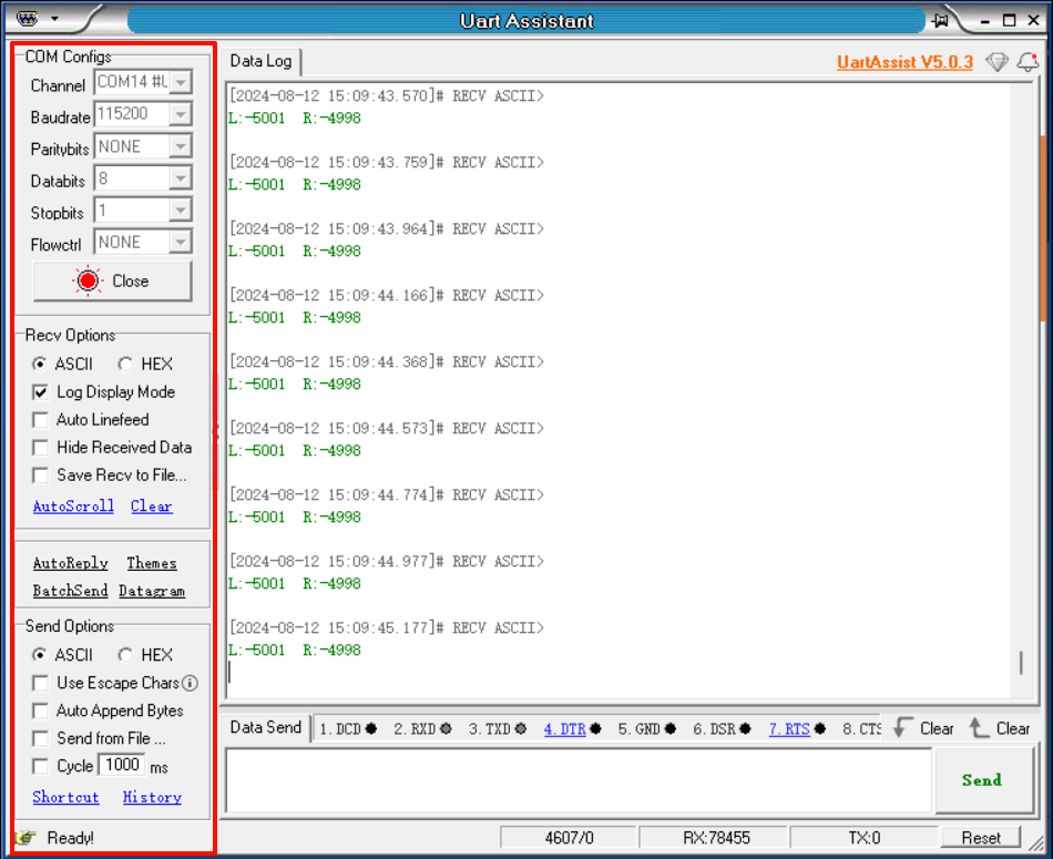
image-20240812151006363

P, PI, PD controller theory
Incremental PID

COMPANY

  • About us
  • Team Style
  • Blog

LEARNING & EXPLORATION

  • Tutorials
  • Edge AI hardware
  • Educational robots
  • Embedded intelligent hardware

WHERE TO BUY

  • Yahboom Online Store
  • Amazon
  • Alibaba
  • AliExpress
  • Mercado

TECHNOLOGY SUPPORT

  • Email: support@yahboom.com

BE A DISTRIBUTOR

  • Email: sales@yahboom.com
QR Code

Copyright © 2017-2026 Yahboom. All Rights Reserved.

EN/中文