Welcome to Self-balancing Robot Car repository
10.I2C Communication(I2C)-OLED
I2C Communication(I2C)-OLED
I2C Communication(I2C)-OLEDHardware connectionControl principleSoftware configurationPin definitionSoftware codeControl functionExperimental phenomenon
The tutorial demonstrates the hardware I2C driving 0.91-inch OLED display to display content.
The tutorial only introduces the standard library project code
Hardware connection
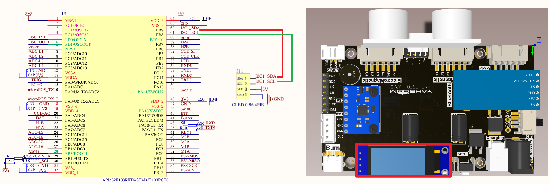
Just install it to the corresponding interface:
| Peripherals | Development Board | Description |
|---|---|---|
| OLED: VCC | 5V | OLED power supply |
| OLED: GND | GND | OLED common ground |
| OLED: SCL | PB8 | Serial clock line (SCL) |
| OLED: SDA | PB9 | Serial data line (SDA) |
Control principle
The I2C (Inter-Integrated Circuit) bus is a serial communication protocol consisting of a serial data line (SDA) and a serial clock line (SCL).
Serial Data Line (SDA): used to transmit data
xxxxxxxxxxAll devices use the same data line to communicate by transmitting data in binary form.
Serial Clock Line (SCL): used to synchronize data transmission
xxxxxxxxxxThe clock line generates pulses at a specific frequency to ensure that both the sending and receiving devices can transmit data at the same timing.
Multi-device communication: The I2C interface uses an address-based device identification mechanism to select a specific device to communicate with.
xxxxxxxxxxEach I2C device has a unique address that identifies the device; the master device selects a specific device to communicate with by sending the device address
I2C communication
IIC bus timing diagram
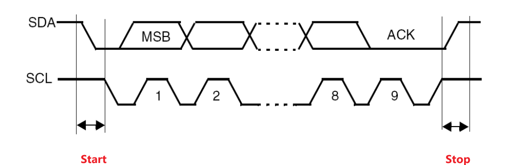
Idle state
SCL high level, SDA high level;
Start condition
SCL high level, SDA falling edge;
Stop condition
SCL high level, SDA rising edge;
Data transmission
SCL low level, SDA rising or falling edge;
Response signal
After receiving data from the device, it will send a low level to the master device to indicate successful reception;
Data validity
When the clock line is high, the data line must remain stable; when the clock line is low, the data line is allowed to change.
xxxxxxxxxxSCL: high level → used for the start and end of communicationSCL: low level → used for data transmission and end
Software configuration
Pin definition
| Main control chip | Pin | Main function (after reset) | Default multiplexing function | Redefine function |
|---|---|---|---|---|
| STM32F103RCT6 | PB8 | PB8 | TIM4_CH3 | I2C1_SCL/CAN_RX |
| STM32F103RCT6 | PB9 | PB9 | TIM4_CH4 | I2C1_SDA/CAN_TX |
Software code
Since the default function of the pin is the ordinary IO pin function, we need to use the redefine function.
xxxxxxxxxxProduct supporting materials source code path: Attachment → Source code summary → 1.Base_Course → 10.I2C
Control function
The tutorial only briefly introduces the code, you can open the project source code to read the details.
OLED_I2C_Init
xvoid OLED_I2C_Init(void){GPIO_InitTypeDef GPIO_InitStructure;I2C_InitTypeDef I2C_InitStructure;RCC_APB1PeriphClockCmd(OLEDI2C_RCC, ENABLE);RCC_APB2PeriphClockCmd(OLED_RCC, ENABLE);// Enable the multiplexing functionRCC_APB2PeriphClockCmd(RCC_APB2Periph_AFIO, ENABLE);GPIO_PinRemapConfig(GPIO_Remap_I2C1, ENABLE);//PB8——SCL PB9——SDAGPIO_InitStructure.GPIO_Mode = GPIO_Mode_AF_OD;GPIO_InitStructure.GPIO_Pin = OLED_SCL_Pin | OLED_SDA_Pin;GPIO_InitStructure.GPIO_Speed = GPIO_Speed_50MHz;GPIO_Init(OLED_Port, &GPIO_InitStructure);I2C_DeInit(OLEDI2C);I2C_InitStructure.I2C_Ack = I2C_Ack_Enable;I2C_InitStructure.I2C_AcknowledgedAddress = I2C_AcknowledgedAddress_7bit;I2C_InitStructure.I2C_ClockSpeed = 400000;I2C_InitStructure.I2C_DutyCycle = I2C_DutyCycle_2;I2C_InitStructure.I2C_Mode = I2C_Mode_I2C;I2C_InitStructure.I2C_OwnAddress1 = 0x10; // Fill in this address casually, do not do slave machineI2C_Init(OLEDI2C, &I2C_InitStructure);I2C_Cmd(OLEDI2C, ENABLE);OLED_Init(); //oled initializationOLED_Draw_Line("oled init success!" , 1, true, true);}
OLED_Draw_String
xxxxxxxxxxvoid OLED_Draw_String(char *data, uint8_t x, uint8_t y, bool clear, bool refresh){if (clear)OLED_Clear();SSD1306_GotoXY(x, y);SSD1306_Puts(data, &Font_7x10, SSD1306_COLOR_WHITE);if (refresh)OLED_Refresh();}
OLED_Draw_Line
xxxxxxxxxxvoid OLED_Draw_Line(char *data, uint8_t line, bool clear, bool refresh){if (line > 0 && line <= 3){OLED_Draw_String(data, 0, 10 * (line - 1), clear, refresh);}}
Experimental phenomenon
The I2c.hex file generated by the project compilation is located in the OBJ folder of the I2C project. Find the corresponding I2c.hex file of the project and use FlyMcu software to download the program into the development board.
After the program is downloaded successfully: OLED will display oled init success! And Hello wrold content.