Welcome to Self-balancing Robot Car repository
17.Lidar wall tracking-multiple walls
Lidar wall tracking-multiple walls
Lidar wall tracking-multiple wallsHardware connectionControl principleMain codeProgram flow chartExperimental phenomenon
The tutorial mainly demonstrates the wall patrol function of the balance car combined with the Tmini-Plus radar (maintaining a certain distance from the nearest wall).
xxxxxxxxxxThe tutorial only introduces the standard library project code
Hardware connection
Since we have configured a special connection line, you only need to install it to the corresponding interface.
| Peripherals | Development Board |
|---|---|
| Tmini-Plus radar: VCC | 5V |
| Tmini-Plus radar: TXD | PC10 |
| Tmini-Plus radar: RXD | PC11 |
| Tmini-Plus radar: GND | GND |
Control principle
The program analyzes the radar data, and sets the distance from the wall and the distance to be maintained for patrolling the wall according to the distance collected by the program initialization (radar 72° distance). The 0° distance determines whether there is an obstacle in front.
xxxxxxxxxxThe right side of the radar needs to be close to the wall, and the angle of distance measurement is 72°
Tmini-Plus radar
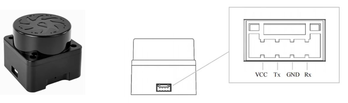
| Product name | Tmini-Plus radar |
|---|---|
| Scanning frequency | 6-12Hz |
| Sampling frequency | 4000 times/s |
| Measuring radius | Black object: 12m |
| Minimum measuring distance | 0.05m |
| Distance measurement principle | TOF distance measurement |
| Scanning angle | 360° |
| Communication interface | Standard asynchronous serial port (UART) 1. Baud rate: 230400 2. Data bits: 8 3. Check bit: None 4. Stop bit: 1 |
| ROS support | ROS1/ROS2 |
| Windows support | Host computer |
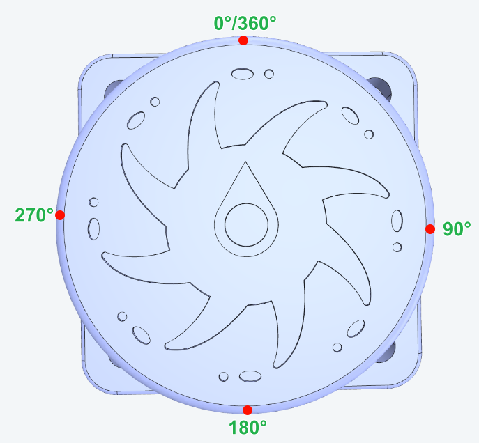
Radar angle distribution
The arrow in the center of the radar points to 0°/360°, and the angle increases clockwise.
Communication protocol
xxxxxxxxxxFor detailed information, please refer to the "T_Mini_Plus Manual"
Main code
The tutorial mainly explains the code for the radar wall following function. For detailed code, please refer to the corresponding project file.
LiDar_Straight
The radar wall following function adds a turning action to the radar wall following function. When there is no obstacle in front of the radar, the radar maintains the wall following function. When an obstacle is detected in front of the radar, the radar turns left.
xxxxxxxxxxvoid LiDar_Straight(void){static u16 target_distance=0;u16 current_distance=target_distance;static u16 Limit_distance=0; // Maximum detection range of radarstatic u16 get_timedis = 0;for (u8 i = 0;i<5;i++) // The detection distance is 72 degrees{if(get_timedis<GET_LidarDIS_Time){if(Tminidis[Lidar_Angle]==0 || Tminidis[Lidar_Angle]>400) continue; // Discard data with values of 0 and greater than 400mmget_timedis ++;target_distance = Tminidis[Lidar_Angle];// Dynamically obtain the target angleLimit_distance=target_distance+200;// 200mm greater than the target distance, mainly to avoid the disappearance of the reference object causing the car to quickly turnif(get_timedis == (GET_LidarDIS_Time-1)){g_lidar_go_flag = 1;get_timedis = GET_LidarDIS_Time;}}if(Tminidis[Lidar_Angle]<(Limit_distance))// Limit the detection range of the radar{current_distance=Tminidis[Lidar_Angle];// Determine distance}}if(get_timedis<GET_LidarDIS_Time) // Do not take any action until the distance is determined{return;}if(Tminidis[0]>0 && Tminidis[0]<Limit_distance)// Determine the obstacle avoidance distance based on the initial value; Because the following distance is 72 degrees, only a left turn is needed{if(lidar_wall_flag == 0){lidar_wall_flag = 1;myTurn_Kd = 30;Move_Z = -600; // turnleftdelay_time_int(1);//10ms}Move_X = 0;Last_error = 0;// Clear PID errors to avoid excessive steeringreturn;}if(get_time_int()!=0){return;}else{if(lidar_wall_flag ==1){lidar_wall_flag = 0;Move_X = 0;Move_Z = 0;myTurn_Kd = 0;return;}}Set_track_speed();Move_Z = Distance_Adjust_PID(current_distance,target_distance);}
Distance_Adjust_PID
PID processing is performed based on the distance between the radar and the wall. If the balancing car does not patrol the wall in a straight line effectively, modify the PID parameters of the app_lidar_car.c file. It is not recommended to modify the PID parameters of the pid_control.c file (the PID parameters of the pid_control.c file are subject to the parameters finally confirmed in the balancing car parameter adjustment tutorial).
xfloat Distance_Adjust_PID(float Current_Distance,float Target_Distance)// PID Distance adjustment PID{error=Target_Distance-Current_Distance; // Calculate deviationOutPut=-Track_Lidar_KP*error-Track_Lidar_KD*(error-Last_error); // Position based PID controllerLast_error=error; // Save last deviationreturn OutPut;}
Program flow chart
Briefly introduce the process of function implementation:
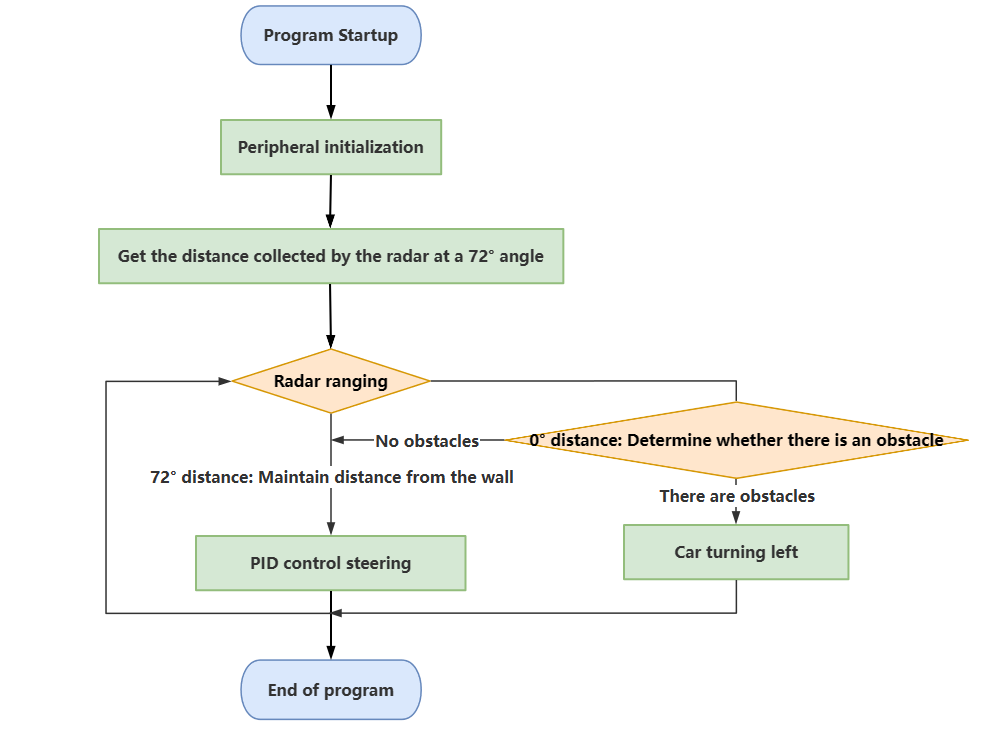
xxxxxxxxxxThe 72° (right side) of the radar is to detect and maintain the distance from the wall. If you encounter an obstacle in front, you only need to turn left
Experimental phenomenon
Software code
The Balance_Radar_wall_line.hex file generated by the project compilation is located in the OBJ folder of the Balance_Radar_wall_line project. Find the Balance_Radar_wall_line.hex file corresponding to the project and use the FlyMcu software to download the program to the development board.
xxxxxxxxxxProduct supporting information source code path: Attachment → Source code summary → 5.Balanced_Car_Extended → 17.Balance_Radar_wall_line
Experimental phenomenon
After the program is started, press KEY1 according to the OLED prompt to start the radar wall-following function of the balance car:
OLED displays wait get dis!: The balance car will take 1 second to obtain the distance that the radar needs to patrol the wall (the right side of the radar needs to be close to the wall, and the source of the patrol distance is the 72° position of the radar); OLED displays start track!: Start the radar wall-following mode.
If an obstacle is encountered during the patrol process, it will turn left; after turning left, it will resume the wall-following mode.
The program has voltage detection. If the voltage is less than 9.6V, the low voltage alarm is triggered and the buzzer will sound.Common situations in which the voltage alarm is triggered:1. The power switch of the development board is not turned on, and only the Type-C data cable is connected for power supply2. The battery pack voltage is lower than 9.6V and needs to be charged in time