Welcome to Self-balancing Robot Car repository
09.CCD module-Reading data (ADC)
CCD module-Reading data (ADC)
CCD module-Reading data (ADC)Hardware connectionControl principleSoftware configurationPin definitionSoftware codeControl functionExperimental phenomenon
The tutorial combines OLED and serial port to display the data output by CCD module.
The tutorial only introduces the standard library project code
Hardware connection
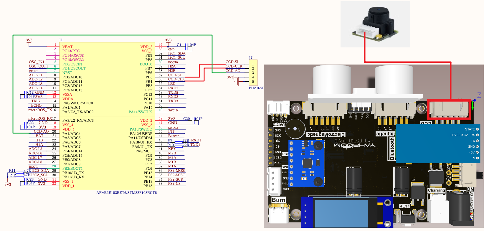
Since we have configured a special connection line, we only need to install it to the corresponding interface:
| Peripherals | Development board |
|---|---|
| CCD: VCC | 3.3V |
| CCD: AO | PA4 |
| CCD: SLK | PB4 |
| CCD: SI | PB5 |
| CCD: GND | GND |
Control principle
CCD module
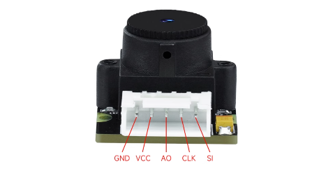
| Peripherals | Description |
|---|---|
| CCD: VCC | Power supply pin: 3.3V-5V |
| CCD: AO | Gray value output pin: analog output |
| CCD: CLK | Clock pin, determines the exposure time and controls the output of pixel gray value. |
| CCD: SI | Controls the acquisition and output of pixel gray value. |
| CCD: GND | Power supply pin: GND |
Working principle
Acquisition timing diagram:
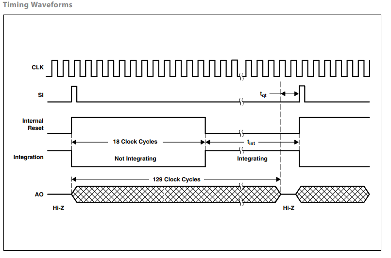
Every 129 clock cycles of TSL1401 is an output acquisition cycle, and the clock cycle is provided by the CLK pin.
When the SI pin receives a high-level signal, the TSL1401 gray value acquisition task and gray value output task start at the same time.
CCD grayscale value acquisition task: perform reset work in the 1st to 18th clock cycles (corresponding to the Internal Reset timing in the figure), perform ambient light sensing in the 19th to 129th clock cycles (corresponding to the Integration timing in the figure), and convert it into an electrical signal. The brighter the environment, the stronger the electrical signal. At the same time, if the clock cycle is longer, the longer the light sensing time, the stronger the electrical signal. The signal collected in the current acquisition cycle is allowed to be read in the next cycle.
CCD grayscale value output task: After each falling edge between the 2nd and 129th cycles, the AO pin outputs a grayscale value once, representing the grayscale value of the 1st to 128th pixels from the left. The value can be read through the microcontroller ADC. Similarly, the signal output in the current output cycle belongs to the signal collected in the previous cycle.
Black line detected
The corresponding grayscale value is low;
White line detected
The corresponding grayscale value is high.
Software configuration
Pin definition
| Main control chip | Pin | Main function (after reset) | Default multiplexing function | Redefine function |
|---|---|---|---|---|
| STM32F103RCT6 | PA4 | PA4 | SPI1_NSS/USART2_CK/DAC_OUT1/ADC12_IN4 | |
| STM32F103RCT6 | PB4 | NJTRST | SPI3_MISO | PB4/TIM3_CH1/SPI1_MISO |
| STM32F103RCT6 | PB5 | PB5 | I2C1_SMBA/SPI3_MOSI/I2S3_SD | TIM3_CH2/SPI1_MOSI |
Software code
We need to configure the pins differently according to the function of the CCD pins.
xxxxxxxxxxProduct supporting materials source code path: Attachment → Source code summary → 2.Extended_Course → 9.CCD
Control function
The tutorial only briefly introduces the code, you can open the project source code to read the details.
ccd_Init
xvoid ccd_Init(void){ADC_InitTypeDef ADC_InitStructure;GPIO_InitTypeDef GPIO_InitStructure;RCC_APB2PeriphClockCmd( CCD_AO_CLK | CCD_ADC_CLK , ENABLE ); //Enable ADC3 channel clockRCC_ADCCLKConfig(RCC_PCLK2_Div6); //Set ADC division factor 6 72M/6=12, ADC maximum time cannot exceed 14M//Set analog channel input pinGPIO_InitStructure.GPIO_Pin = CCD_AO_PIN;GPIO_InitStructure.GPIO_Mode = GPIO_Mode_AIN; //Analog input pinGPIO_Init(CCD_AO_PORT, &GPIO_InitStructure);//Initialize SI interfaceRCC_APB2PeriphClockCmd( CCD_SI_CLK , ENABLE ); GPIO_InitStructure.GPIO_Mode = GPIO_Mode_Out_PP; //Push-pull output GPIO_InitStructure.GPIO_Pin = CCD_SI_PIN; GPIO_InitStructure.GPIO_Speed ••= GPIO_Speed_10MHz; GPIO_Init(CCD_SI_PORT,&GPIO_InitStructure); //Initialize CLK interface RCC_APB2Per iphClockCmd( CCD_CLK_CLK , ENABLE ); GPIO_InitStructure.GPIO_Mode = GPIO_Mode_Out_PP; //Push-pull output GPIO_InitStructure.GPIO_Pin = CCD_CLK_PIN; GPIO_InitStructure.GPIO_Speed ••= GPIO_Speed_10MHz; GPIO_Init(CCD_CLK_PORT,&GPIO_InitStructure);ADC_DeInit(CCD_ADC); //Reset ADC2 and reset all registers of peripheral ADC2 to default valuesADC_InitStructure.ADC_Mode = ADC_Mode_Independent; //ADC working mode: ADC1 and ADC2 work in independent modeADC_InitStructure.ADC_ScanConvMode = DISABLE; //Analog-to-digital conversion works in single-channel modeADC_InitStructure.ADC_ContinuousConvMode = DISABLE; //Analog-to-digital conversion works in single-conversion modeADC_InitStructure.ADC_ExternalTrigConv = ADC_ExternalTrigConv_None; //Conversion is started by software instead of external triggerADC_InitStructure.ADC_DataAlign = ADC_DataAlign_Right; //ADC data right-alignedADC_InitStructure.ADC_NbrOfChannel = 1; //Number of ADC channels for sequential regular conversionADC_Init(CCD_ADC, &ADC_InitStructure); //Initialize the registers of the peripheral ADCx according to the parameters specified in ADC_InitStructADC_Cmd(CCD_ADC, ENABLE); //Enable the specified ADC1ADC_ResetCalibration(CCD_ADC); //Enable reset calibrationwhile(ADC_GetResetCalibrationStatus(CCD_ADC)); //Wait for reset calibration to endADC_StartCalibration(CCD_ADC); //Start AD calibrationwhile(ADC_GetCalibrationStatus(CCD_ADC)); //Wait for calibration to end}
Get_Adc_CCD
xxxxxxxxxxu16 Get_Adc_CCD(u8 ch){//Sets the specified ADC rule group channel, one sequence, and sampling time//Sets the specified ADC rule group channel, one sequence, and sampling time//ADC1, ADC channel, sampling time is 480 cyclesADC_RegularChannelConfig(CCD_ADC, ch, 1, ADC_SampleTime_239Cycles5 ); //ADC1, ADC channel, sampling time is 239.5 cycles//Enable the specified ADC1 software transformation startup function//Enable the specified ADC1 software conversion startup functionADC_SoftwareStartConvCmd(CCD_ADC, ENABLE);//Wait for the conversion to finish//Wait for the conversion to finishwhile(!ADC_GetFlagStatus(CCD_ADC, ADC_FLAG_EOC ));//Returns the result of the last ADC1 rule group conversion//Returns the most recent conversion result of the ADC1 rule groupreturn ADC_GetConversionValue(CCD_ADC);}
RD_TSL
xxxxxxxxxxvoid RD_TSL(void){u8 i=0,tslp=0;TSL_CLK=1;TSL_SI=0;Dly_us();TSL_SI=1;TSL_CLK=0;Dly_us();TSL_CLK=1;TSL_SI=0;Dly_us();for(i=0;i<128;i++){TSL_CLK=0;Dly_us();Dly_us();ADV[tslp]=(Get_Adc_CCD(CCD_ADC_CH))>>4;++tslp;TSL_CLK=1;Dly_us();}}
Find_CCD_Zhongzhi
xxxxxxxxxxvoid Find_CCD_Zhongzhi(void){static u16 i,j,Left,Right;static u16 value1_max,value1_min;value1_max=ADV[0]; //Dynamic threshold algorithm, read the maximum and minimum valuesfor(i=5;i<123;i++) //Remove 5 points on each side{if(value1_max<=ADV[i])value1_max=ADV[i];}value1_min=ADV[0]; //Minimum valuefor(i=5;i<123;i++){if(value1_min>=ADV[i])value1_min=ADV[i];}CCD_Yuzhi=(value1_max+value1_min)/2; //Calculate the threshold for this midline extractionfor(i = 5;i<118; i++) //Find the left jump edge{if(ADV[i]>CCD_Yuzhi&&ADV[i+1]>CCD_Yuzhi&&ADV[i+2]>CCD_Yuzhi&&ADV[i+3]<CCD_Yuzhi&&ADV[i+4]<CCD_Yuzhi&&ADV[i+5]<CCD_Yuzhi){Left=i;break;}}for(j = 118;j>5; j--){if(ADV[j]<CCD_Yuzhi&&ADV[j+1]<CCD_Yuzhi&&ADV[j+2]<CCD_Yuzhi&&ADV[j+3]>CCD_Yuzhi&&ADV[j+4]>CCD_Yuzhi&&ADV[j+5]>CCD_Yuzhi){Right=j;break;}}CCD_Zhongzhi=(Right+Left)/2;}
CCD_Get_ADC_128X32
xxxxxxxxxxuint8_t* CCD_Get_ADC_128X32(void){RD_TSL();for (int i = 0; i < 128; i++){ADC_128X32[i] = ADV[i] >> 3;}return ADC_128X32;}
OLED_Show_CCD_Image
xxxxxxxxxxvoid OLED_Show_CCD_Image(uint8_t* p_img){OLED_Clear();for (int i = 0; i < 128; i++){if (p_img[i] < 32){SSD1306_DrawPixel(i, p_img[i], SSD1306_COLOR_WHITE);}}OLED_Refresh();}
Experimental phenomenon
The CCD.hex file generated by the project compilation is located in the OBJ folder of the CCD project. Find the CCD.hex file corresponding to the project and use the FlyMcu software to download the program into the development board.
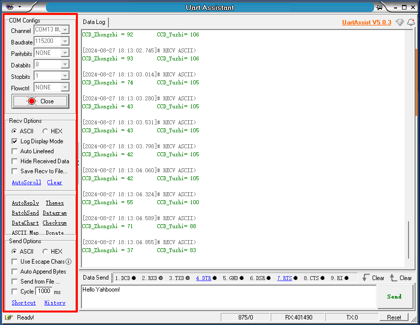
After the program is successfully downloaded: OLED and serial port display the data output by the CCD module, and OLED displays the CCD module data in the form of a curve.
xxxxxxxxxxWhen using the serial port debugging assistant, you need to pay attention to the serial port settings. If the settings are wrong, the phenomenon may be inconsistent.