yahboom
HomeLearn
Solution
Blog
Online Store
About Us
EN/中文
Self-balancing Robot Car📖
00.Get started quickly
  • 01.Balance car manual
  • 02.Balancing car assembly
  • 03.Get started quickly
  • 04.Balance car interface description
  • 05.Common Problem Analysis
  • 06.Balance Car V2 Library Function Development Manual
01.Environment development
  • 01.MDK-ARM installation
  • 02.STM32CubeIDE installation
  • 03.Common driver installation
  • 04.Download the program
  • 05.MDK-ARM project usage
  • 06.Program simulation
  • 07. VSCode Installation
02.STM32 getting started course
  • 01.Project creation
  • 02.LED Control(GPIO)
  • 03.Buzzer control(GPIO)
  • 04.Button control(EXTI)
  • 05.Serial communication(USART)
  • 06.Voltage detection(ADC)
  • 07.Basic timer(TIM)
  • 08.Universal timer(TIM)
  • 09.Advanced Timer(TIM)
  • 10.I2C Communication(I2C)-OLED
  • 11.SPI communication(SPI)-2.4G handle
  • 12.Independent Watchdog (IWDG)
  • 13.Window Watchdog (WWDG)
  • 14.DMA-USART
  • 15.DMA-I2C
03.STM32 expansion course
  • 01.Battery voltage detection (ADC)
  • 02.Ultrasonic module-measuring distance (TIM)
  • 03.Motor drive+encoder (TIM)
  • 04.OLED Data-Display(I2C)
  • 05.MPU6050-Data Read (I2C)
  • 06.Bluetooth module-Data reading (USART)
  • 07.2.4G handle-Data reading (SPI)
  • 08.Tracking module-Read status (GPIO)
  • 09.CCD module-Reading data (ADC)
  • 10.Electromagnetic module-Reading data (ADC)
  • 11.K210 module-Serial communication (USART)
  • 12.Tmini-Plus lidar-Reading data (USART)
04.Robot car PID control course
  • 01.PID basic concept
  • 02.PID example analysis
  • 03.P, PI, PD controller theory
  • 04.Position PID
  • 05.Incremental PID
  • 06.Cascade PID
  • 07.Balance principle of car
  • 08.Car upright control (PD)
  • 09.Car speed ​​control (PI)
  • 10.Car steering control (PD)
  • 11.Got angle and angular velocity (DMP algorithm)
  • 12.Got angle and angular velocity (Kalman filter algorithm)
  • 13.Got angle and angular velocity(Complementary filter algorithm)
05.Robot car basic course
  • 01.Car parameter adjustment
  • 02.Ultrasonic obstacle avoidance
  • 03.Ultrasonic follow
  • 04.Bluetooth remote control
  • 05.Load balance
06.Robot car advanced course
  • 01.4-channel tracking
  • 02.4-channel tracking avoid
  • 03.2.4G handle control
  • 04.CCD tracking
  • 05.CCD tracking avoid
  • 06.Electromagnetic tracking
  • 07.K210-QR code recognition
  • 08.K210-Color line tracking
  • 09.K210-Color follow
  • 10.K210-Self learning
  • 11.K210-Number recognition
  • 12.Lidar avoid
  • 13.Lidar guard
  • 14.Lidar follow
  • 15.Lidar patrol
  • 16.Lidar wall tracking-straight line
  • 17.Lidar wall tracking-multiple walls
  • 18. DIY Automatic driving car
07.Robot car LQR control
  • Robot car LQR control
08.Circuit design
  • 01.Overall circuit design
  • 02.STM32 minimum system
  • 03.Serial port circuit design
  • 04.Power circuit design
  • 05.MPU6050 Circuit Design
  • 06.Motor drive circuit design
09.Mathematical model
  • Mathematical model
10.Expand course
  • Autonomous Driving
Download
  • APP(Android)
  • Codes
  • Hardware-Info
  • SCH
  • Software Tools
  • STM32_Chip_DataSheet
  • 3D_Model_File
  • Video_PPT
Download ZIP

Welcome to Self-balancing Robot Car repository

07.Basic timer(TIM)

Basic timer

Basic timerHardware connectionControl principleSoftware configurationSoftware codeControl functionExperimental phenomenon

The tutorial demonstrates how to use the basic timer (TIM6) to control the onboard LED on the development board to flash.

The tutorial only introduces the standard library project code

Hardware connection
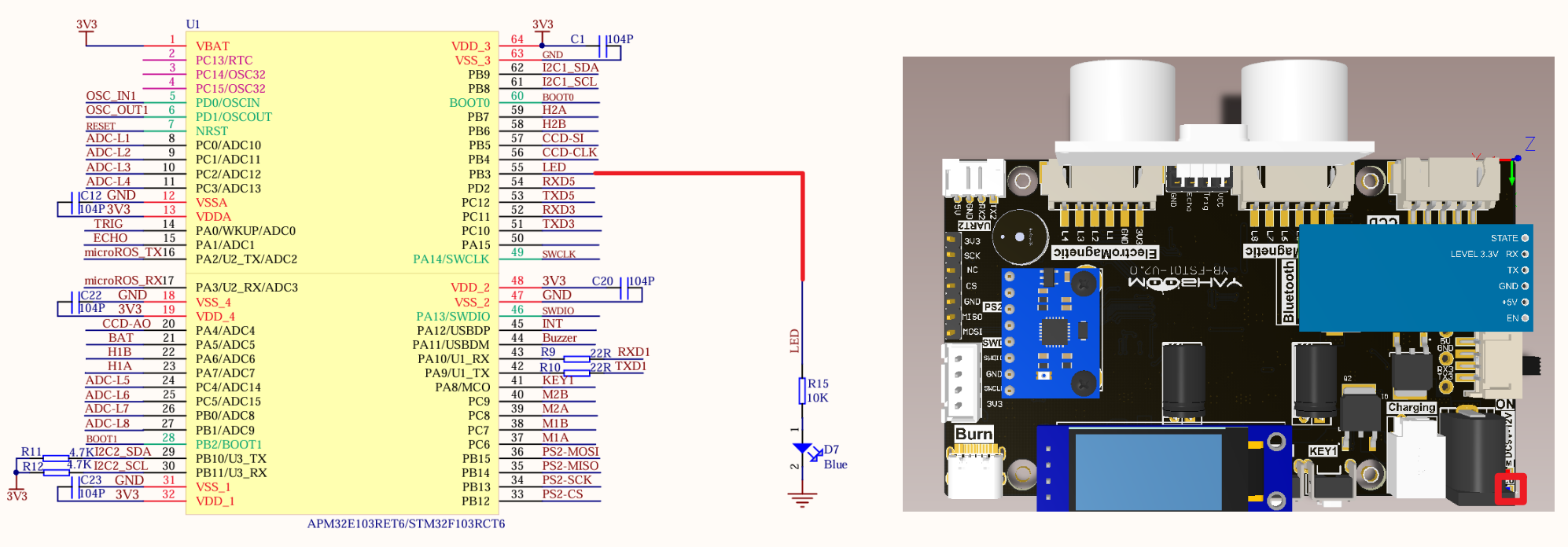
image-20240825204024431

PeripheralsDevelopment boardDescription
LEDPB3The anode of the LED is connected to the development board PB3, and the cathode is connected to the development board GND

Control principle

Use the timing function of TIM6 on the STM32F103RCT6 development board

Use the GPIO output function to control the LED and implement the timing function through the basic timer.

  • Basic timer

Use the timing function of TIM6 on the STM32F103ZET6 development board

Timer typeBasic timer
Timer nameTIM6, TIM7
Counter bit number16
Counting modeIncrementing
Prescaler coefficient1-65536
Generate DMA requestYes
Capture/compare channel0
Complementary outputNone
Clock frequency72MHz (maximum)
Mount busAPB1

Time base unit

RegisterFunction
Counter register (TIMx_CNT)Current count value of the counter
Prescaler register (TIMx_PSC)Set the scaler coefficient (1-65536)
Auto-reload register (TIMx_ARR)Counter count boundary and reload value

Timing formula

T(s)=(ARR+1)∗(PSC+1)TIM_CLK(Hz)
ParameterMeaning
T(s)Timing time, in seconds
ARRAuto-reload value
PSCPrescaler coefficient
TIM_CLKTimer clock, in Hz

Timing time for this project: 10ms

T(s)=(ARR+1)∗(PSC+1)TIM_CLK(Hz)=(99+1)∗(7199+1)72000000(Hz)=0.01s

Software configuration

Software code

Configure the timing function of the basic timer TIM6, without configuring specific pins.

xxxxxxxxxx
Product supporting materials source code path: Attachment → Source code summary → 1.Base_Course → 7.Base_Time

Control function

The tutorial only briefly introduces the code, you can open the project source code to read it.

TIM6_Init

​x
void TIM6_Init(void)
{
    TIM_TimeBaseInitTypeDef TIM_TimeBaseStructure;
    NVIC_InitTypeDef NVIC_InitStructure;
    RCC_APB1PeriphClockCmd(RCC_APB1Periph_TIM6, ENABLE); //Enable the timer clock
    TIM_TimeBaseStructure.TIM_Prescaler = 7199; //Prescaler
    TIM_TimeBaseStructure.TIM_Period = 99; //Set the counter auto-reload value
    TIM_TimeBaseInit(TIM6, &TIM_TimeBaseStructure);
    TIM_ClearFlag(TIM6, TIM_FLAG_Update); //Clear the update flag of TIM
    TIM_ITConfig(TIM6, TIM_IT_Update, ENABLE);

    //Interrupt priority NVIC settings
    NVIC_InitStructure.NVIC_IRQChannel = TIM6_IRQn; //TIM6 interrupt
    NVIC_InitStructure.NVIC_IRQChannelPreemptionPriority = 4; //Preempt priority level 4
    NVIC_InitStructure.NVIC_IRQChannelSubPriority = 2; //From priority level 2
    NVIC_InitStructure.NVIC_IRQChannelCmd = ENABLE; //IRQ channel is enabled
    NVIC_Init(&NVIC_InitStructure); //Initialize NVIC registers

    TIM_Cmd(TIM6, ENABLE);
}

TIM6_IRQHandler

xxxxxxxxxx
void TIM6_IRQHandler(void)
{
    if (TIM_GetITStatus(TIM6, TIM_IT_Update) != RESET) //Check whether TIM update interrupt occurs
    {
        TIM_ClearITPendingBit(TIM6, TIM_IT_Update); //Clear TIMx update interrupt flag
        led_count++; //LED service display flag
        cotrol_led();//Light service 3 seconds within the light flash 3 times
    }
}

cotrol_led

xxxxxxxxxx
void cotrol_led(void)
{
    if(!led_flag)
    {
        if(led_count>300)//3S
        {
            led_count = 0;
            led_flag = 1;
        }
    }
else
{
    if(led_count>20)//200ms
    {
        led_count = 0;
        LED = !LED;//State inversion
        led_twinkle_count++;
    if(led_twinkle_count == 6)
    {
        LED = 0;
        led_twinkle_count = 0;
        led_flag = 0;
    }
}
}

Experimental phenomenon

The Base_Time.hex file generated by the project compilation is located in the OBJ folder of the Base_Time project. Find the Base_Time.hex file corresponding to the project and use the FlyMcu software to download the program into the development board.

After the program is successfully downloaded: the LED flashes three times every 3 seconds.

Voltage detection(ADC)
Universal timer(TIM)

COMPANY

  • About us
  • Team Style
  • Blog

LEARNING & EXPLORATION

  • Tutorials
  • Edge AI hardware
  • Educational robots
  • Embedded intelligent hardware

WHERE TO BUY

  • Yahboom Online Store
  • Amazon
  • Alibaba
  • AliExpress
  • Mercado

TECHNOLOGY SUPPORT

  • Email: support@yahboom.com

BE A DISTRIBUTOR

  • Email: sales@yahboom.com
QR Code

Copyright © 2017-2026 Yahboom. All Rights Reserved.

EN/中文