Welcome to Self-balancing Robot Car repository
05.Load balance
Load balance
Load balanceLoad balancing principleSoftware implementation principleParameter adjustment stepsProgram flow chartExperimental phenomenon
The tutorial mainly adds the function of load balancing based on Bluetooth remote control.
xxxxxxxxxxThe tutorial only introduces the standard library project code
Load balancing principle
The load actually changes the original balance state of the balance car, and the balance car parameters need to be readjusted.
Software implementation principle
Balance mode switching
Control the load and non-load balance mode switching through buttons.
PID parameter switching
By setting the load mode flag bit, determine whether the final output data of the upright ring, speed ring, and steering ring needs to be multiplied by the load balance coefficient.
xxxxxxxxxxExample:int Balance_PD(float Angle,float Gyro){float Angle_bias,Gyro_bias;int balance;Angle_bias=Mid_Angle-Angle;Gyro_bias=0-Gyro;balance=-Balance_Kp/100*Angle_bias-Gyro_bias*Balance_Kd/100;if(weight_mode_flag == 1) // Load mode switch{balance = balance*Balance_K;}return balance;}
Parameter adjustment steps
The program needs to switch to the corresponding balance mode before it can adjust the parameters:
First adjust the PID parameters of the non-load balance state: For specific parameter adjustment methods, refer to the "Balance Car Parameter Adjustment" tutorial in this chapter
Note: The parameters for debugging the non-load balance state are PID parameters, not PID parameter coefficients.
xxxxxxxxxxPID parameters are located in the source code: pid_control.cCode example:// Non-adjustment area: PID parameter coefficientsfloat Balance_K = 2.0;float Velocity_K = 1.35;float Turn_K = 1.0;// Adjustment area: PID parameters// Vertical ring PD control parametersfloat Balance_Kp = 9600;float Balance_Kd = 75;// Speed ring PI control parametersfloat Velocity_Kp=7000;float Velocity_Ki=35;// Turning ring PD control parametersfloat Turn_Kp=1400;float Turn_Kd=30;
Debug the normal Bluetooth control in the non-load balancing state
Debug the PID parameter coefficient of the load balancing state: For specific parameter adjustment methods, refer to the "Balance Car Parameter Adjustment" tutorial in this chapter
Note: The parameter for debugging the load balancing state is the PID parameter coefficient, not the PID parameter.
xxxxxxxxxxPID parameters are located in the source code: pid_control.cCode example:// Adjustment area: PID parameter coefficientsfloat Balance_K = 2.0;float Velocity_K = 1.35;float Turn_K = 1.0;// Non-adjustment area: PID parameters// Vertical ring PD control parametersfloat Balance_Kp = 9600;float Balance_Kd = 75;// Speed ring PI control parametersfloat Velocity_Kp=7000;float Velocity_Ki=35;// Turning ring PD control parametersfloat Turn_Kp=1400;float Turn_Kd=30;
Program flow chart
Briefly introduce the process of function implementation:
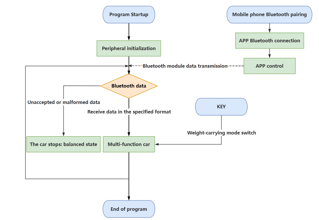
Experimental phenomenon
Software code
The weight_control.hex file generated by the project compilation is located in the OBJ folder of the weight_control project. Find the weight_control.hex file corresponding to the project and use the FlyMcu software to download the program into the development board.
xxxxxxxxxxProduct supporting information source code path: Attachment → Source code summary → 4.Balanced_Car_base → 05.weight_control
Experimental phenomenon
After the program is started, press the KEY1 button according to the OLED prompt to start the balance car Bluetooth control function: OLED will display the balance car load mode and balance car inclination in real time!
KEY1 button: In this program, you can start the balance car Bluetooth control function and control the switch of the balance car load mode.
There will be a buzzer prompt sound when switching to load mode.
The program has voltage detection. If the voltage is less than 9.6V, the low voltage alarm will be triggered and the buzzer will sound.Common situations for triggering voltage alarm:1. The power switch of the development board is not turned on, and only the Type-C data cable is connected for power supply2. The battery pack voltage is lower than 9.6V and needs to be charged in time