yahboom
HomeLearn
Solution
Blog
Online Store
About Us
EN/中文
MicroROS-Pi5📖
01. Introduction
  • 0.Unpacking and reviewing video
  • 1. ReadMe - learning route
  • 2. Introduction to lidar
  • 3. Introduction to microROS control board
  • 4. FAQ
  • 5. About charging
02. Assembly course
  • Assembly steps
03. Preparation
  • First Trial
  • 1. Write firmware
  • 2. MicroROS control board parameter configuration
  • 3. Connect to MicroROS agent
  • 4. Connect to WIFI in hotspot mode
04. Quick start control course
  • 1. Self start handle control
  • 2. Close the self-starting handle control process
  • 3. Quick start keyboard control
  • 4. Map navigation and APP control
05. Robot basic course
  • 1. Robot information release
  • 2. Robot keyboard control
  • 3. Robot handle control
  • 4. Robot state estimation
  • 5. Linear speed calibration
  • 6. Angular velocity calibration
  • 7. Robot URDF model
06. ROS+OpenCV course
  • 1. Getting started with Opencv CV
  • 2. Geometric transformation
  • 3. Image processing and drawing
  • 4. Open Source CV image beautification
  • 5. QR code creation and recognition
  • 6. AR vision
  • 7. ROS+Opencv application
07. Mediapipe course
  • 1. Hand detection
  • 2. Posture detection
  • 3. Overall detection
  • 4. Face detection
  • 5. Face recognition
  • 6. Face effects
  • 7. 3D object recognition
  • 8. Brush
  • 9. Finger control
  • 10 .Gesture recognition
08. Robot visual interaction
  • 1. Monocular camera calibration
  • 2. Color tracking
  • 3. Object recognition and tracking
  • 4. Face recognition tracking
  • 5. Autonomous driving line patrol
  • 6. QR code motion control
  • 7. Gesture control of basic movement of the car
  • 8. Control the car movement with your palm
  • 9. Gesture control car action group
  • 10. Palm control of the two-dimensional gimbal servo
09. Lidar course
  • 1. Lidar avoid
  • 2. Lidar following
  • 3. Lidar guard
  • 4. Lidar patrol
  • 5. Gmapping mapping
  • 6. Cartographer mapping
  • 7. Navigation2 navigation avoid
  • 8. ROS Robot APP mapping
  • 9. ROS Robot APP navigation
10. Multi-machine course
  • 1. Multi-machine handle control
  • 2. Multi-machine keyboard control
  • 3. Multi-machine navigation
11. Linux basic course
  • 1. Introduction to Linux system
  • 2. Ubuntu file system
  • 3. Ubuntu common commands
  • 4. Ubuntu common editors
  • 5. Ubuntu software operation commands
  • 6. Virtual machine installation
  • 7. SSH remote control
  • 8. VNC remote control
  • 9. Transfer files remotely
  • 10. Driver library and communication
  • 11. Static IP and hotspot mode
  • 12. Bind device ID
  • 13. Capacity expansion and resource allocation
  • 14. Update system software sources
  • 15. Set root user password
  • 16. sudo free password
  • 17. Connect to WiFi network
  • 18. View system version
  • 19. Customized service management
  • 20. Back up system image
12. RPi basic setting course
  • 1. Update and upgrade operating system
  • 2. Introduction to raspi-config tool
  • 3. config.txt file description
  • 4. Network Configuration
  • 5. remote access
  • 6. Transfer files remotely
  • 7. Set display resolution and rotation
  • 8. Set screen to sleep
  • 9. Get real-time temperature of Raspberry Pi
  • 10. Play audio and video
  • 11. Using USB camera
  • 12. Using MIPI camera
13. Docker course
  • 1. Overview and installation
  • 2. Common commands
  • 3. Docker images deeply understand and publish images
  • 4. Docker hardware interaction and data processing
  • 5. Enter the robot's docker container
14. ROS2 basic course
  • 1. Introduction to ROS2
  • 2. ROS2 install Humble
  • 3. ROS2 development environment
  • 4. ROS2 workspace
  • 5. ROS2 function package
  • 6. ROS2 node
  • 7.ROS2 topic communication
  • 8.ROS2 service communication
  • 9.ROS2 action communication
  • 10.ROS2 custom interface message
  • 11.ROS2 parameter service case
  • 12.ROS2 meta-function package
  • 13.ROS2 distributed communication
  • 14.ROS2 DDS
  • 15.ROS2 time related API
  • 16.ROS2 common command tools
  • 17.ROS2 rviz2 use
  • 18.ROS2 rqt toolbox
  • 19.ROS2 Launch startup file configuration
  • 20.ROS2 recording and playback tool
  • 21.ROS2 URDF model
  • 22.ROS2 Gazebo simulation platform
  • 23.ROS2 TF2 coordinate transformation
15. microROS control board development environment
  • 1. Introduction to microROS control board
  • 2. Set up ESP32-IDF development environment
  • 3. ESP32-IDF configuration tool
  • 4. Install ESP32-microros components
  • 5. Install and start microROS agent
  • 6. Flash-tool burning firmware
16. ESP32 basic course
  • 1. Turn on the LED light
  • 2. Button function
  • 3. Drive the buzzer
  • 4. Serial communication
  • 5. Battery voltage detection
  • 6. Drive PWM servo
  • 7. Drive motor
  • 8. Read motor encoder data
  • 9. PID controls car speed
  • 10. Read IMU data
  • 11. Read radar data
  • 12. Flash access data
  • 13. Partition table and memory
  • 14. Bluetooth communication
  • 15. WiFi networking
  • 16. Robot kinematics analysis
  • 17.ROS-WiFi camera module
17. microROS basic course
  • 1. Publish topic
  • 2. Subscribe topic
  • 3. Multi-topic subscribe and publish
  • 4. Subscribe buzzer topics
  • 5. Subscribe PWM servo topics
  • 6. Subscribe speed control topics
  • 7. Release speed topic
  • 8. Release IMU data topic
  • 9. Publish lidar data topics
  • 10. Customized transmission method
Download
  • Mapping_APP(iOS_Android)
  • Source code
  • Hardware information
  • VM image file
  • RPi5 imgae file
  • Instruction Manual
  • 3D Model File
  • ROS2_Basic_VM
Download ZIP
FAQ
  • 1、1.USB camera abnormal termination

Welcome to MicroROS-Pi5 repository

当製品の日本語版マニュアル資料は、こちらからご取得ください。

21.ROS2 URDF model

21. ROS2 URDF Model

1. Introduction to URDF

The modeling method in ROS is called URDF, which stands for Unified Robot Description Format. It not only clearly describes the robot model itself, but also describes the robot's external environment. URDF model files use the XML format.

SolidWorks model to URDF plugin: sw_urdf_exporter - ROS Wiki

2. Robot Components

When modeling and describing a robot, we first need to be familiar with the robot's components and parameters. For example, a robot is generally composed of four major components: hardware structure, drive system, sensor system, and control system. Common robots on the market, whether mobile robots or robotic arms, can be broken down into these four components.
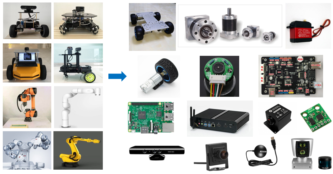
image-20220528144350325

  • The hardware structure refers to the tangible components, such as the chassis, housing, and motors.
  • The drive system is the equipment that enables these components to function properly, such as the motor driver and power management system.
  • The sensor system includes encoders on the motor, an onboard IMU, installed cameras, radar, and more, enabling the robot to sense its own state and external environment.
  • The control system is the primary vehicle for our development process, typically a computing platform like a Raspberry Pi or a computer, along with its operating system and application software.

The robot modeling process follows a similar approach, using a modeling language to clearly describe each component of the robot and then assemble them.

3. URDF Syntax

3.1. Link Description

The tag is used to describe the appearance and physical properties of a robot's rigid body. Appearance includes size, color, and shape, while physical properties include mass, inertia matrix, collision parameters, and so on.
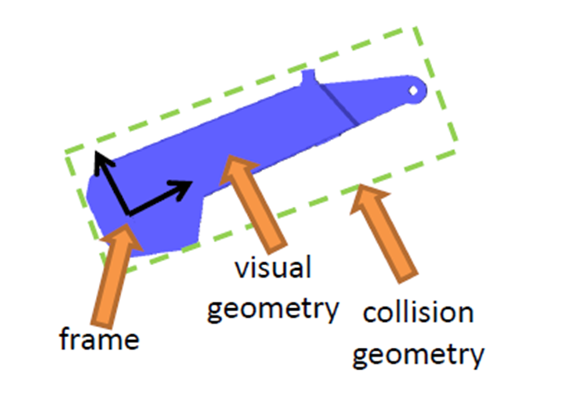
image-20220528144534685

Taking this robotic arm link as an example, its link description is as follows:
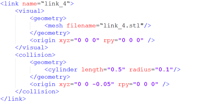
image-20220528144549092

The name in the link tag represents the name of the link. We can customize it, and this name will be used when connecting joints to links in the future.

The section of the link describes the robot's appearance. For example:

  • represents the geometric shape. is used to call a pre-designed blue appearance in 3D software. This is the STL file, which looks identical to the real robot.
  • represents the offset of the coordinate system relative to the initial position, including translation in the x, y, and z directions, and roll, pitch, and raw rotations. If no offset is required, all values are 0.

The second section, , describes the collision parameters. While the content appears to be the same as , including and , there are actually significant differences.

  • focuses on describing the robot's appearance, that is, its visual effects.
  • describes the robot's state during motion, such as how contact with the outside world is considered a collision.

In this robot model, the blue part is described using . In actual control, such a complex appearance requires high computational power for collision detection. To simplify the calculations, we've simplified the collision detection model to a cylinder outlined in green, which is the shape described by in . The coordinate system offset is similar and can describe the offset of the rigid body's center of mass.
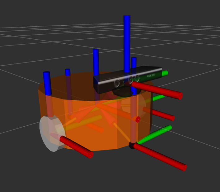
image-20220528144603646

For mobile robots, links can also be used to describe the body, wheels, and other components of the robot.

3.2 Joint Description

Rigid bodies in a robot model must ultimately be connected through joints to generate relative motion.

Joints in URDF have six types of motion.
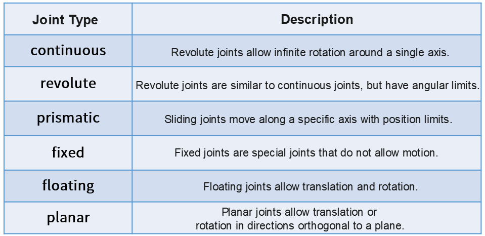
image-20220528144655899

  1. Continuous: This describes rotational motion. It can rotate infinitely around a specific axis. For example, the wheels of a cart fall into this category.
  2. Revolute: This is also a revolute joint. Unlike the continuous type, it cannot rotate infinitely but has angle limits. For example, the two links in a robotic arm fall into this category.
  3. Prismatic: This is a sliding joint. It can translate along a specific axis and also has position limits. Linear motors typically use this type of motion.
  4. Fixed: This is the only type of joint that doesn't allow for movement, but it's still quite commonly used. For example, a camera link mounted on a robot doesn't change its relative position. In this case, the connection type used is Fixed.
  5. Floating: This is a floating joint. The sixth type, Planar, is a planar joint. These two are relatively less commonly used.
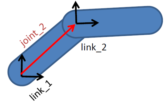
image-20220528144722751

In a URDF model, each link is described using an XML file, such as the name of the joint and the type of motion.
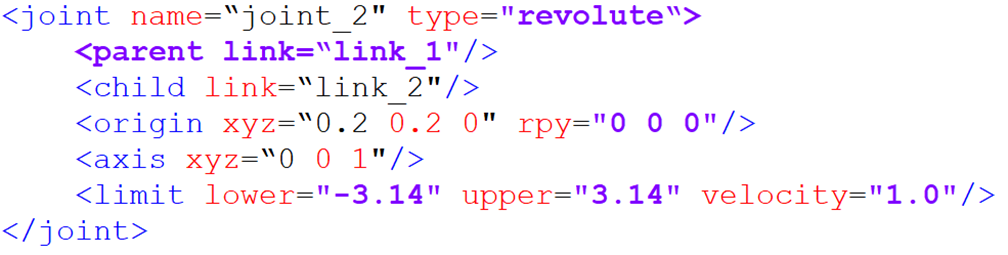
image-20220528144729633

  • parent tag: describes the parent link;
  • child tag: describes the child link, which moves relative to the parent link;
  • origin: indicates the relationship between the two link coordinate systems, represented by the red vector in the image, which can be understood as how the two links are mounted together;
  • axis: indicates the unit vector of the joint's motion axis. For example, if z is equal to 1, the rotation is about the positive z-axis;
  • limit: indicates any limitations on the motion, such as minimum position, maximum position, and maximum speed.

4. Complete Robot Model
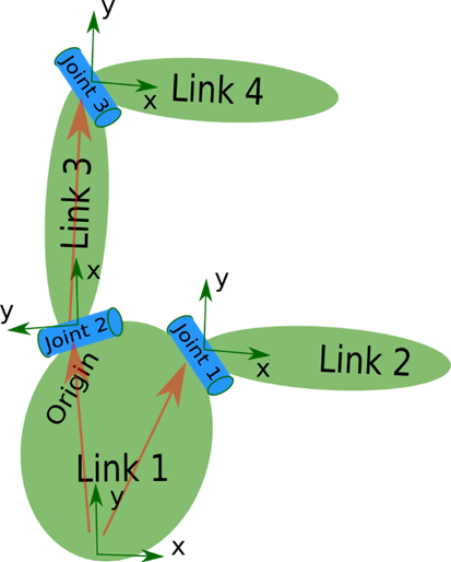
image-20220528144900705

Finally, all the link and joint tags describe and combine each part of the robot. Placed within a single robot tag, this forms the complete robot model.
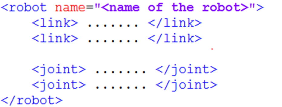
image-20220528144824234

So, when looking at a URDF model, don't rush to delve into the details of each block of code. First, look for links and joints to understand the robot's components. Once you understand the overall picture, then delve into the details.

4.1. Creating a Robot Model

Using the muto model as an example, copy the yahboomcar_description package from this tutorial's folder to the src directory of your workspace:
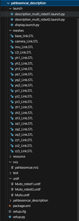
image-20250905184735806

  • urdf: Stores the robot model's URDF or XACR file
  • meshes: Stores the model rendering files referenced in the URDF
  • launch: Stores the relevant startup files
  • rviz: Stores the Rviz configuration file

Then compile the package.

xxxxxxxxxx
colcon build --packages-select yahboomcar_description
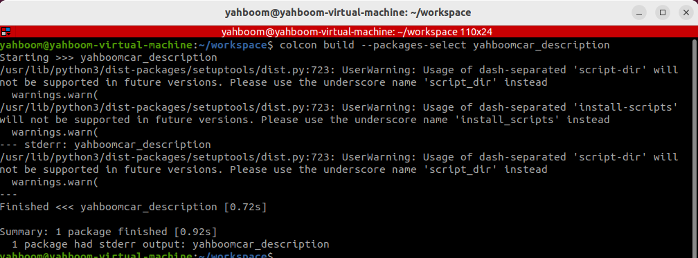
image-20250905184908066

4.2. Model Visualization

  • Refresh the environment variables and run the launch command.
xxxxxxxxxx
ros2 launch yahboomcar_description display.launch.py

Rviz will automatically launch and display the robot model:
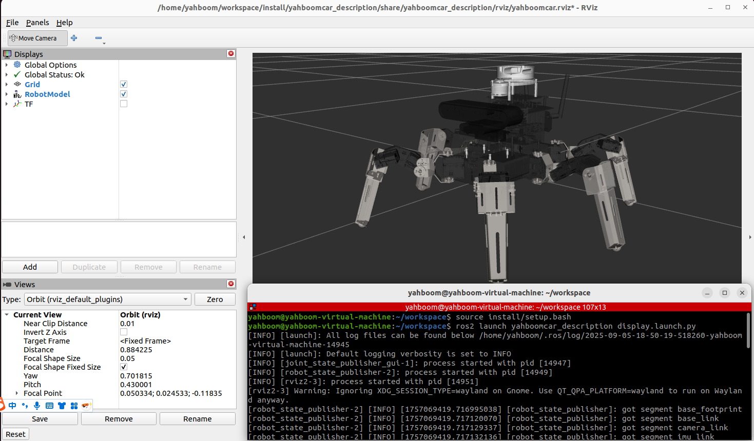
image-20250905185113862

ROS2 recording and playback tool
ROS2 Gazebo simulation platform

COMPANY

  • About us
  • Team Style
  • Blog

LEARNING & EXPLORATION

  • Tutorials
  • Edge AI hardware
  • Educational robots
  • Embedded intelligent hardware

WHERE TO BUY

  • Yahboom Online Store
  • Amazon
  • Alibaba
  • AliExpress
  • Mercado

TECHNOLOGY SUPPORT

  • Email: support@yahboom.com

BE A DISTRIBUTOR

  • Email: sales@yahboom.com
QR Code
QR Code

Copyright © 2017-2026 Yahboom. All Rights Reserved.

EN/中文