Welcome to MicroROS-Pi5 repository
当製品の日本語版マニュアル資料は、こちらからご取得ください。
1. Introduction to microROS control board
Introduction to microROS control board
The microROS control board is a lightweight ROS2 driver controller and an ESP32S3 dual-core development board. The board integrates important peripherals such as the ESP32S3 core module control unit, motor driver, steering gear driver, and six-axis IMU attitude sensor.It supports WiFi, Bluetooth, serial port and other communication functions, supports four encoder motors, two PWM servos and one laser radar. It also has a PD power supply powered by Raspberry Pi 5. The peripheral driver firmware comes with the factory, and users can directly access the ROS2 environment for use. It is convenient to operate, simple and efficient to use.
Onboard resource description
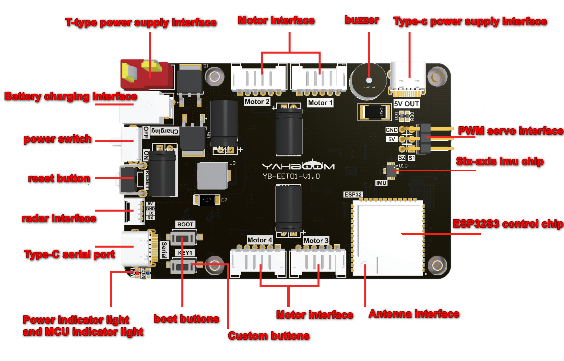
Battery power supply interface: Connect a 7.4V battery (T-shaped interface) to power the robot.
Battery charging interface: Connect the DC8.4V charger to charge the robot.
Power switch: main power switch of the robot.
Reset button: The reset button of the ESP32S3 control chip.
Radar interface: connect to MS200 laser radar.
Type-C serial port: used for burning firmware, configuring parameters, serial communication and other functions.
Power indicator light and MCU indicator light: indicate the current status of the product.
BOOT button: The BOOT button of the ESP32S3 control chip can also be used as a custom button.
Custom buttons: GPIO of ESP32S3 control chip, programmable custom functions.
Motor interface: connect to 310 encoder motor.
Antenna interface: connect external antenna.
ESP32S3 control chip: The main control chip of the microROS control board, which is responsible for managing all peripheral functions on the board.
Six-axis IMU chip: Provides the current attitude information of the robot.
PWM servo interface: used to connect two PWM servos.
Type-C power supply interface: Connect to the Type-C interface of Raspberry Pi 5 to power Raspberry Pi 5.
Buzzer: active buzzer, used for low voltage alarm prompts.
GPIO pin assignments
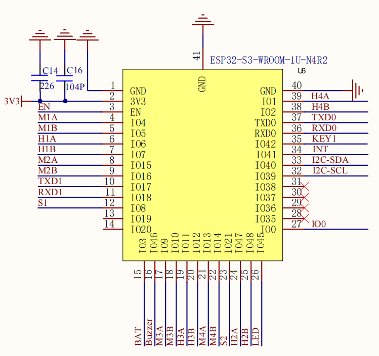
| Peripheral name | ESP32-S3-GPIO |
|---|---|
| Motor M1-PWM-M1A | GPIO4 |
| Motor M1-PWM-M1B | GPIO5 |
| Motor M1-Encoder-H1A | GPIO6 |
| Motor M1-Encoder-H1B | GPIO7 |
| Motor M2-PWM-M2A | GPIO15 |
| Motor M2-PWM-M2B | GPIO16 |
| Motor M2-Encoder-H2A | GPIO47 |
| Motor M2-Encoder-H2B | GPIO48 |
| Motor M3-PWM-M3A | GPIO9 |
| Motor M3-PWM-M3B | GPIO10 |
| Motor M3-Encoder-H3A | GPIO11 |
| Motor M3-Encoder-H3B | GPIO12 |
| Motor M4-PWM-M4A | GPIO13 |
| Motor M4-PWM-M4B | GPIO14 |
| Motor M4-Encoder-H4A | GPIO1 |
| Motor M4-Encoder-H4B | GPIO2 |
| BOOT button-IO0 | GPIO0 |
| Custom buttons-KEY1 | GPIO42 |
| Battery voltage detection-BAT | GPIO3 |
| MCU indicator light-LED | GPIO45 |
| Buzzer | GPIO46 |
| Servo interface-S1 | GPIO8 |
| Servo interface-S2 | GPIO21 |
| IMU interruption-INT | GPIO41 |
| IMU-I2C-SCL | GPIO39 |
| IMU-I2C-SDA | GPIO40 |
| Radar RX-serial port 1-TXD1 | GPIO17 |
| Radar TX-serial port 1-RXD1 | GPIO18 |
| TypeC flash serial port RX-TXD0 | GPIO43 |
| TypeC flash serial port TX-RXD0 | GPIO44 |