Welcome to MicroROS-Pi5 repository
当製品の日本語版マニュアル資料は、こちらからご取得ください。
9. Publish lidar data topics
Publish lidar data topics
Publish lidar data topics1. Experimental purpose2. Hardware connection3. Core code analysis4. Compile, download and flash firmware5. Experimental results
1. Experimental purpose
Learn ESP32-microROS components, access the ROS2 environment, and publish radar data topics.
2. Hardware connection
As shown in the figure below, the microROS control board integrates the ESP32-S3-WROOM core module, which has its own wireless WiFi function. The ESP32-S3 core module needs to be connected to an antenna. It also integrates the MS200 lidar serial port interface, which requires an external MS200 lidar. To complete the experiment, you still need to connect the type-C data cable to the computer and the microROS control board for the firmware burning function.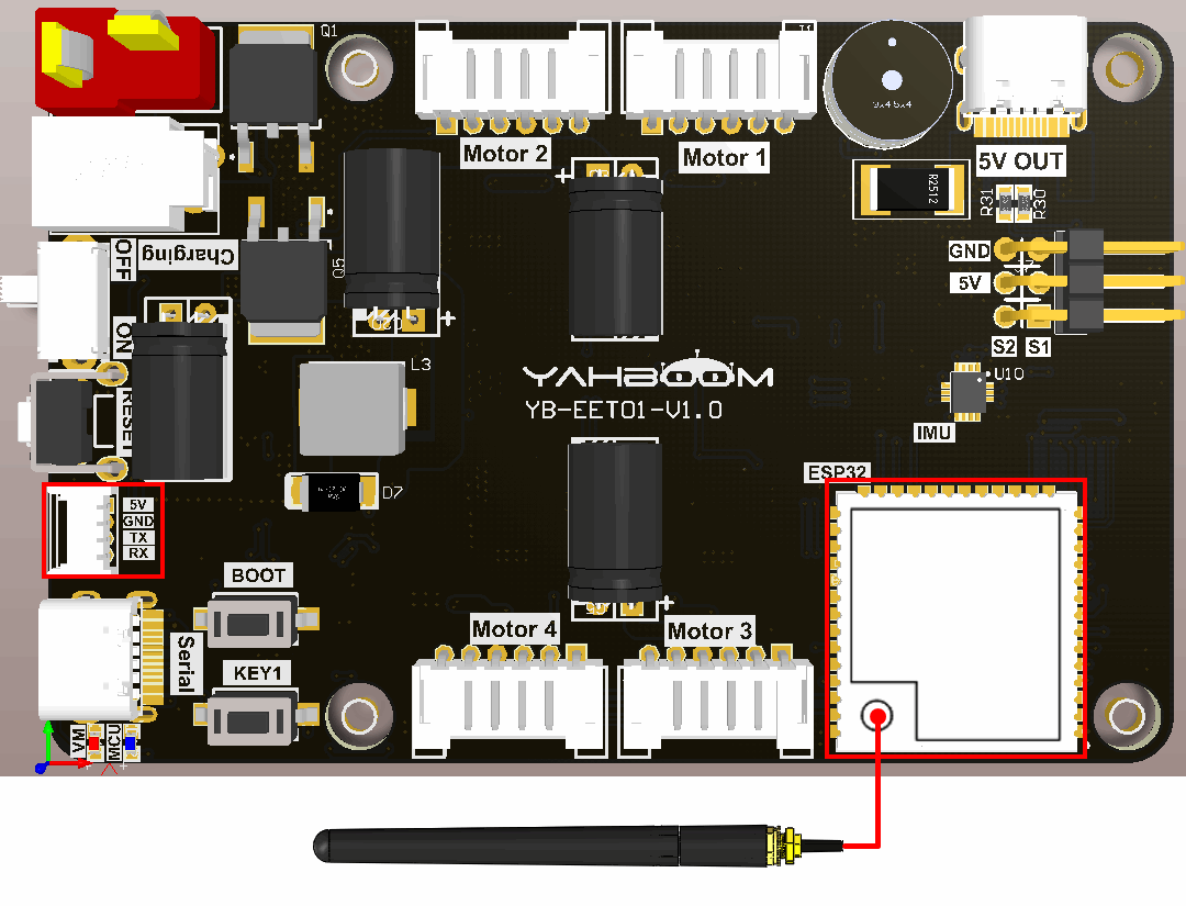
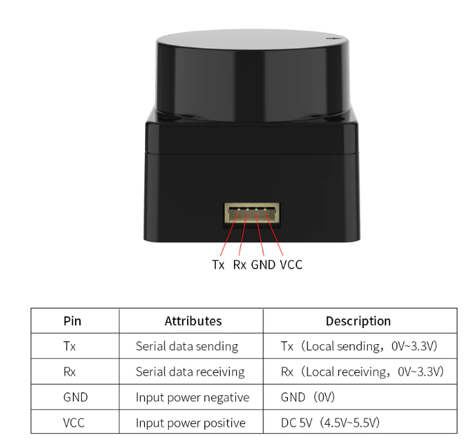
The MS200 lidar interface cable has an anti-reverse connection function and can be inserted directly into the interface.
3. Core code analysis
The virtual machine path corresponding to the program source code is as follows.
~/esp/Samples/microros_samples/lidar_publisher
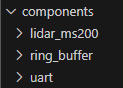
Since the MS200 lidar is used this time, and the components of the MS200 lidar have been made in the previous routine, the relevant components of the MS200 lidar need to be copied to the components directory of the project. Call Uart1_Init and Lidar_Ms200_Init at the beginning of the program to initialize serial port 1 and MS200 lidar.
Initialize the release of lidar information, set the radar angle to -180~180, the angle spacing to 1 degree, the ranging range to 0.12~8.0 meters, and frame_id to "laser_frame". Then decide whether to add the ROS_NAMESPACE prefix based on whether ROS_NAMESPACE is empty.
xxxxxxxxxxvoid lidar_ros_init(void){int i;msg_lidar.angle_min = -180*M_PI/180.0;msg_lidar.angle_max = 180*M_PI/180.0;msg_lidar.angle_increment = 1*M_PI/180.0;msg_lidar.range_min = 0.12;msg_lidar.range_max = 8.0;msg_lidar.ranges.data = (float *)malloc(360 * sizeof(float));msg_lidar.ranges.size = 360;for (i = 0; i < msg_lidar.ranges.size; i++){msg_lidar.ranges.data[i] = 0;}msg_lidar.intensities.data = (float *)malloc(360 * sizeof(float));msg_lidar.intensities.size = 360;for (i = 0; i < msg_lidar.intensities.size; i++){msg_lidar.intensities.data[i] = 10.0;}char* content_frame_id = "laser_frame";int len_namespace = strlen(ROS_NAMESPACE);int len_frame_id_max = len_namespace + strlen(content_frame_id) + 2;// ESP_LOGI(TAG, "lidar frame len:%d", len_frame_id_max);char* frame_id = malloc(len_frame_id_max);if (len_namespace == 0){// ROS命名空间为空字符// The ROS namespace is empty characterssprintf(frame_id, "%s", content_frame_id);}else{// 拼接命名空间和frame id// Concatenate the namespace and frame idsprintf(frame_id, "%s/%s", ROS_NAMESPACE, content_frame_id);}msg_lidar.header.frame_id = micro_ros_string_utilities_set(msg_lidar.header.frame_id, frame_id);free(frame_id);}
Create a new lidar data update task to update the radar data every 20 milliseconds.
xxxxxxxxxxvoid lidar_update_data_task(void *arg){uint16_t distance_mm[MS200_POINT_MAX] = {0};uint8_t intensity[MS200_POINT_MAX] = {0};uint16_t index = 0;int i = 0;while (1){index = 0;for (i = 0; i < MS200_POINT_MAX; i++){distance_mm[i] = Lidar_Ms200_Get_Distance(i);intensity[i] = Lidar_Ms200_Get_Intensity(i);}for (i = 0; i < MS200_POINT_MAX; i++){index = (MS200_POINT_MAX-i) % MS200_POINT_MAX;if (index >= 180){index = (index - 180) % MS200_POINT_MAX;}else{index = (index + 180) % MS200_POINT_MAX;}msg_lidar.ranges.data[i] = (float)(distance_mm[index] / 1000.0);msg_lidar.intensities.data[i] = (float)(intensity[index]);}vTaskDelay(pdMS_TO_TICKS(20));}vTaskDelete(NULL);}
Get the WiFi name and password to connect from the IDF configuration tool.
xxxxxxxxxx#define ESP_WIFI_SSID CONFIG_ESP_WIFI_SSID#define ESP_WIFI_PASS CONFIG_ESP_WIFI_PASSWORD#define ESP_MAXIMUM_RETRY CONFIG_ESP_MAXIMUM_RETRY
The uros_network_interface_initialize function will connect to WiFi hotspots based on the WiFi configuration in IDF.
xxxxxxxxxxESP_ERROR_CHECK(uros_network_interface_initialize());
Then obtain ROS_NAMESPACE, ROS_DOMAIN_ID, ROS_AGENT_IP and ROS_AGENT_PORT from the IDF configuration tool.
xxxxxxxxxx#define ROS_NAMESPACE CONFIG_MICRO_ROS_NAMESPACE#define ROS_DOMAIN_ID CONFIG_MICRO_ROS_DOMAIN_ID#define ROS_AGENT_IP CONFIG_MICRO_ROS_AGENT_IP#define ROS_AGENT_PORT CONFIG_MICRO_ROS_AGENT_PORT
Initialize the configuration of microROS, in which ROS_DOMAIN_ID, ROS_AGENT_IP and ROS_AGENT_PORT are modified in the IDF configuration tool according to actual needs.
xrcl_allocator_t allocator = rcl_get_default_allocator();rclc_support_t support;// 创建rcl初始化选项// Create init_options.rcl_init_options_t init_options = rcl_get_zero_initialized_init_options();RCCHECK(rcl_init_options_init(&init_options, allocator));// 修改ROS域ID// change ros domain idRCCHECK(rcl_init_options_set_domain_id(&init_options, ROS_DOMAIN_ID));// 初始化rmw选项// Initialize the rmw optionsrmw_init_options_t *rmw_options = rcl_init_options_get_rmw_init_options(&init_options);// 设置静态代理IP和端口// Setup static agent IP and portRCCHECK(rmw_uros_options_set_udp_address(ROS_AGENT_IP, ROS_AGENT_PORT, rmw_options));
Try to connect to the proxy. If the connection is successful, go to the next step. If the connection to the proxy is unsuccessful, you will always be in the connected state.
xxxxxxxxxxwhile (1){ESP_LOGI(TAG, "Connecting agent: %s:%s", ROS_AGENT_IP, ROS_AGENT_PORT);state_agent = rclc_support_init_with_options(&support, 0, NULL, &init_options, &allocator);if (state_agent == ESP_OK){ESP_LOGI(TAG, "Connected agent: %s:%s", ROS_AGENT_IP, ROS_AGENT_PORT);break;}vTaskDelay(pdMS_TO_TICKS(500));}
Create the node "lidar_publisher", in which ROS_NAMESPACE is empty by default and can be modified in the IDF configuration tool according to actual conditions.
xxxxxxxxxxrcl_node_t node;RCCHECK(rclc_node_init_default(&node, "lidar_publisher", ROS_NAMESPACE, &support));
To create publisher "scan", you need to specify the publisher information as sensor_msgs/msg/LaserScan type.
xxxxxxxxxxRCCHECK(rclc_publisher_init_default(&publisher_lidar,&node,ROSIDL_GET_MSG_TYPE_SUPPORT(sensor_msgs, msg, LaserScan),"scan"));
Create a publisher's timer with a publishing frequency of 11HZ.
xconst unsigned int timer_timeout = 90;RCCHECK(rclc_timer_init_default(&timer_lidar,&support,RCL_MS_TO_NS(timer_timeout),timer_lidar_callback));
Create an executor, where the three parameters are the numbers controlled by the executor, which should be greater than or equal to the number of subscribers and publishers added to the executor. and add the publisher's timer to the executor.
xxxxxxxxxxrclc_executor_t executor;int handle_num = 1;RCCHECK(rclc_executor_init(&executor, &support.context, handle_num, &allocator));RCCHECK(rclc_executor_add_timer(&executor, &timer_lidar));
The main function of the lidar timer callback function is to send LaserScan data.
xxxxxxxxxxvoid timer_lidar_callback(rcl_timer_t *timer, int64_t last_call_time){RCLC_UNUSED(last_call_time);if (timer != NULL){struct timespec time_stamp = get_timespec();msg_lidar.header.stamp.sec = time_stamp.tv_sec;msg_lidar.header.stamp.nanosec = time_stamp.tv_nsec;RCSOFTCHECK(rcl_publish(&publisher_lidar, &msg_lidar, NULL));}}
Call rclc_executor_spin_some in the loop to make microros work normally.
xxxxxxxxxxwhile (1){rclc_executor_spin_some(&executor, RCL_MS_TO_NS(100));usleep(1000);}
4. Compile, download and flash firmware
Use a Type-C data cable to connect the virtual machine/computer and the microROS control board. If the system pops up, choose to connect to the virtual machine.
Activate the ESP-IDF development environment. Note that every time you open a new terminal, you need to activate the ESP-IDF development environment before compiling the firmware.
xxxxxxxxxxsource ~/esp/esp-idf/export.sh
Enter the project directory
xxxxxxxxxxcd ~/esp/Samples/microros_samples/lidar_publisher
Open the ESP-IDF configuration tool.
xxxxxxxxxxidf.py menuconfig
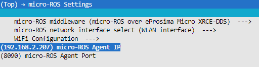
Open micro-ROS Settings, fill in the IP address of the agent host in micro-ROS Agent IP, and fill in the port number of the agent host in micro-ROS Agent Port.
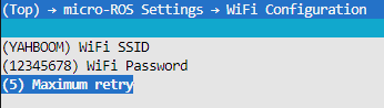
Open micro-ROS Settings->WiFi Configuration in sequence, and fill in your own WiFi name and password in the WiFi SSID and WiFi Password fields.
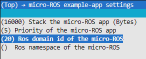
Open the micro-ROS example-app settings. The Ros domain id of the micro-ROS defaults to 20. If multiple users are using it at the same time in the LAN, the parameters can be modified to avoid conflicts. Ros namespace of the micro-ROS is empty by default and does not need to be modified under normal circumstances. If non-empty characters (within 10 characters) are modified, the namespace parameter will be added before the node and topic.
After modification, press S to save, and then press Q to exit the configuration tool.
Compile, flash, and open the serial port simulator.
xxxxxxxxxxidf.py build flash monitor
If you need to exit the serial port simulator, press Ctrl+].
5. Experimental results
After powering on, ESP32 tries to connect to the WiFi hotspot, and then tries to connect to the proxy IP and port.
If the agent is not turned on in the virtual machine/computer terminal, please enter the following command to turn on the agent. If the agent is already started, there is no need to start the agent again.
xxxxxxxxxxdocker run -it --rm -v /dev:/dev -v /dev/shm:/dev/shm --privileged --net=host microros/micro-ros-agent:humble udp4 --port 8090 -v4

After the connection is successful, a node and a publisher are created.

At this time, you can open another terminal in the virtual machine/computer and view the /lidar_publisher node.
xxxxxxxxxxros2 node listros2 node info /lidar_publisher
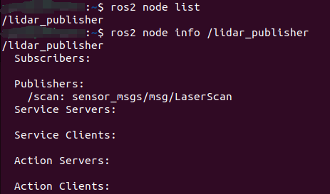
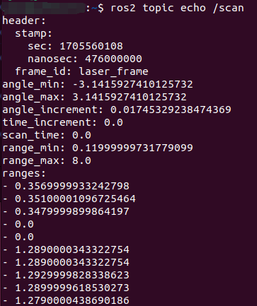
Subscribe/scan topic data,
xxxxxxxxxxros2 topic echo /scan
Press Ctrl+C to end the command
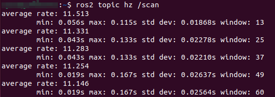
Check the frequency of /scan topic. It is normal if it is about 11hz.
xxxxxxxxxxros2 topic hz /scan
Press Ctrl+C to end the command