Welcome to MicroROS-Pi5 repository
当製品の日本語版マニュアル資料は、こちらからご取得ください。
1. Turn on the LED light
Turn on the LED light
Turn on the LED light1. Experimental purpose2. Hardware connection3. Core code analysis4. Compile and download the burning firmware5. Experimental results
1. Experimental purpose
Control the LED indicator light on the microROS control board to flash.
2. Hardware connection
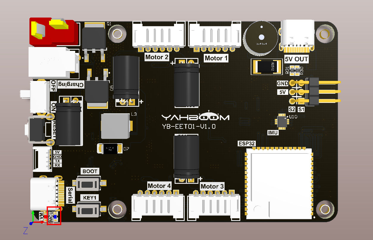
As shown in the figure below, the LED indicator is an onboard component and does not require the connection of other external devices. Just connect the computer and microROS control board with a Type-C data cable to realize the firmware flashing function.
3. Core code analysis
The virtual machine path corresponding to the program source code is:
~/esp/Samples/esp32_samples/led
Initialize the LED peripherals, where LED_GPIO corresponds to GPIO45 of the hardware circuit, and the GPIO mode is the output mode.
xvoid Led_Init(void){// zero-initialize the config structure.gpio_config_t io_conf = {};//disable interrupt 禁用中断io_conf.intr_type = GPIO_INTR_DISABLE;//set as output mode 设置为输出模式io_conf.mode = GPIO_MODE_OUTPUT;//bit mask of the pins that you want to set 引脚编号设置io_conf.pin_bit_mask = (1ULL<<LED_GPIO);//disable pull-down mode 禁用下拉io_conf.pull_down_en = 0;//disable pull-up mode 禁用上拉io_conf.pull_up_en = 0;//configure GPIO with the given settings 配置GPIO口gpio_config(&io_conf);// 关闭LED灯Led_Off();}
Turn on the LED light
xxxxxxxxxxvoid Led_On(void){gpio_set_level(LED_GPIO, LED_ACTIVE_LEVEL);}
Turn off the LED light
xxxxxxxxxxvoid Led_Off(void){gpio_set_level(LED_GPIO, !LED_ACTIVE_LEVEL);}
Control the status of the LED light. If the state is passed to 0, the LED light will be off. If the state is passed to 1, the LED light will be on.
xxxxxxxxxxvoid Led_State(uint8_t state){if (state == 0){gpio_set_level(LED_GPIO, !LED_ACTIVE_LEVEL);}else{gpio_set_level(LED_GPIO, LED_ACTIVE_LEVEL);}}
The LED flashes and needs to be called every 10 milliseconds. interval represents the interval time, the unit is 10ms.
xxxxxxxxxxvoid Led_Flash(uint16_t interval){static uint16_t state = 0;static uint16_t count = 0;count++;if (count >= interval){count = 0;state = (state + 1) % 2;Led_State(state);}}
Call the Led_Init function in app_main, and continue to call the Led_Flash function to make the LED flash.
xLed_Init();while (1){Led_Flash(50);vTaskDelay(pdMS_TO_TICKS(10));}
4. Compile and download the burning firmware
Use a Type-C data cable to connect the virtual machine/computer and the microROS control board. If the system pops up, choose to connect to the virtual machine.
Activate the ESP-IDF development environment. Note that every time you open a new terminal, you need to activate the ESP-IDF development environment before compiling the firmware.
xxxxxxxxxxsource ~/esp/esp-idf/export.sh
Enter the project directory
xxxxxxxxxxcd ~/esp/Samples/esp32_samples/led
Compile, burn, and open the serial port simulator
xxxxxxxxxxidf.py build flash monitor
If you need to exit the serial port simulator, press Ctrl+].
5. Experimental results
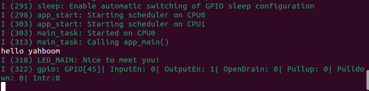
The serial port simulator prints the greeting "hello yahboom" and the MCU indicator light flashes every 0.5 seconds.