Welcome to RDK X5 Board repository
5.Robot calibration
5、Robot calibration
After starting the program, combined with the encoder on the car, we can calibrate the linear and angular velocities of the car by adjusting the parameters
1、Run sample code
Taking our company's product Rosmaster-X3 as an example, the terminal enters the following command to start,
#Drive of chassis trolleyros2 launch yahboomcar_bringup yahboomcar_bringup_X3_launch.py#Calibrate the linear speed of the carros2 run yahboomcar_bringup calibrate_linear_X3#Calibrated angular velocityros2 run yahboomcar_bringup calibrate_angular_X3#Dynamic parameter adjustmentros2 run rqt_reconfigure rqt_reconfigure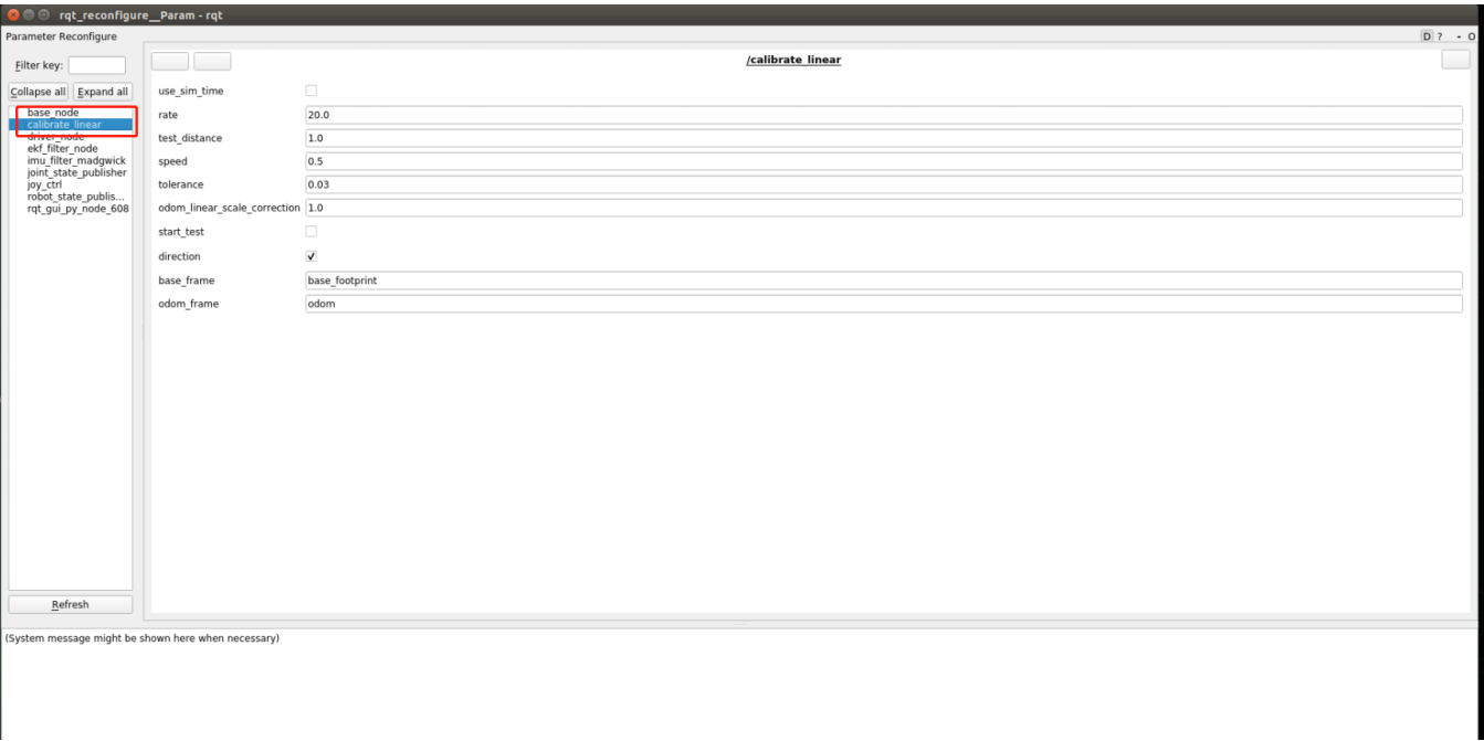
Taking the calibration of linear speed as an example, click on "start_test" to calibrate the linear speed in the x-direction of the car, and observe whether the car has moved the test_ The distance is set to 1m by default. The distance that can be customized for testing before calibration must be a decimal. After setting, click on the blank space and the program will automatically write it in. If the distance the car moves exceeds the acceptable error range (the value of the tolerance variable), then set odom_ Linear_ Scale_ The value of correction. The following are the meanings of each parameter.
| parameter | Parameter Description |
|---|---|
| rate | Release frequency (without modification) |
| test_distance | Test line speed distance |
| speed | The magnitude of linear velocity |
| tolerance | The size of acceptable error values |
| odim_linear_scale_correction | Coefficient of proportion |
| start_test | start test |
| direction | Direction (Linear speed test X (1) Y (0) direction) |
| base_frame | Monitor the parent coordinates of TF transformation |
| odom_frame | Monitor the sub coordinates of TF changes |
The variable settings for testing angular velocity are generally consistent, but it is a test_ Distance changed to test_ Angle test angle and speed has changed to angular velocity size.
2、Analysis of program core source code
This program mainly uses TF to monitor the transformation between coordinates, by monitoring the base_ Coordinate transformation between footprint and odom to let the robot know "how far I have traveled/how many degrees I have turned"
xxxxxxxxxx#Monitoring TF transformationdef get_position(self): try: now = rclpy.time.Time() trans = self.tf_buffer.lookup_transform(self.odom_frame,self.base_frame,now) return trans except (LookupException, ConnectivityException, ExtrapolationException): self.get_logger().info('transform not ready') raise return#Obtain the current xy coordinates and calculate the distance based on the previous xy coordinatesself.position.x = self.get_position().transform.translation.xself.position.y = self.get_position().transform.translation.yprint("self.position.x: ",self.position.x)print("self.position.y: ",self.position.y)distance = sqrt(pow((self.position.x - self.x_start), 2) + pow((self.position.y - self.y_start), 2))distance *= self.odom_linear_scale_correctionCalibrate_ Angular_ The core code of X3 is as follows,
x#Here we also monitor TF transformation and obtain the current position and attitude information, but here we also do transformation, which converts Quaternion to Euler angles,and then we'll go back
def get_odom_angle(self): try: now = rclpy.time.Time() rot = self.tf_buffer.lookup_transform(self.odom_frame,self.base_frame,now) #print("oring_rot: ",rot.transform.rotation) cacl_rot = PyKDL.Rotation.Quaternion(rot.transform.rotation.x, rot.transform.rotation.y, rot.transform.rotation.z, rot.transform.rotation.w) #print("cacl_rot: ",cacl_rot) angle_rot = cacl_rot.GetRPY()[2] #print("angle_rot: ",angle_rot) except (LookupException, ConnectivityException, ExtrapolationException): self.get_logger().info('transform not ready') return#Calculate rotation angleself.odom_angle = self.get_odom_angle()self.delta_angle = self.odom_angular_scale_correction *self.normalize_angle(self.odom_angle - self.first_angle)The published TF transformation is in base_ The code path for the node published by this node is as follows,
xxxxxxxxxx~/driver_ws/src/yahboomcar_base_node/src/base_node_X3
This node will receive/vel_ Raw's data, through mathematical calculations, was released for odom data, while TF transformation was also released. The core code is as follows,
xxxxxxxxxx//Calculate the value of xy coordinate and xyzw Quaternion. The xy two-point coordinate represents the position, and the xyzw Quaternion represents the attitude
double delta_heading = angular_velocity_z_ * vel_dt_; //radiansdouble delta_x = (linear_velocity_x_ * cos(heading_)-linear_velocity_y_*sin(heading_)) * vel_dt_; //mdouble delta_y = (linear_velocity_x_ *sin(heading_)+linear_velocity_y_*cos(heading_)) * vel_dt_; //mx_pos_ += delta_x;y_pos_ += delta_y;heading_ += delta_heading;tf2::Quaternion myQuaternion;geometry_msgs::msg::Quaternion odom_quat ;myQuaternion.setRPY(0.00,0.00,heading_ );geometry_msgs::msg::TransformStamped t;rclcpp::Time now = this->get_clock()->now();t.header.stamp = now;t.header.frame_id = "odom";t.child_frame_id = "base_footprint";t.transform.translation.x = x_pos_;t.transform.translation.y = y_pos_;t.transform.translation.z = 0.0;t.transform.rotation.x = myQuaternion.x();t.transform.rotation.y = myQuaternion.y();t.transform.rotation.z = myQuaternion.z();t.transform.rotation.w = myQuaternion.w();tf_broadcaster_->sendTransform(t);