Welcome to RDK X5 Robot repository
3. Key control buzzer sound
3. The key controls the buzzer
3. The key controls the buzzer3.1. Experimental purpose3.2. Configure pin information3.3. Analysis of experimental flow chart3.4. Add file structure3.5. Core code interpretation3.6. Hardware connection3.7. Experimental effect
3.1. Experimental purpose
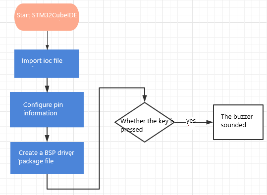
Detect the KEY1 status on the extension board and control the buzzer to sound.The buzzer sounds every time the key is pressed.
3.2. Configure pin information
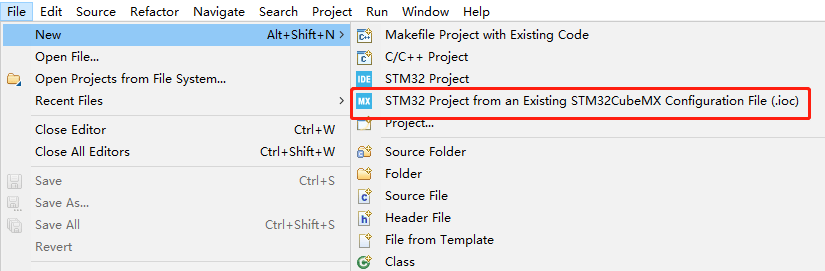
Since each new project needs configuration information, it is troublesome. Fortunately, STM32CubeIDE provides the function of importing.IOC file, which can help us save time.
Import ioc file from LED project and name it BEEP.
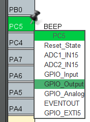
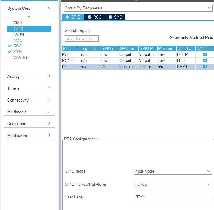
According to the schematic diagram, the control pin of the buzzer is connected to the PC5 pin of the STM32 chip. Set PC5 to GPIO_Output mode and change the Label to BEEP. Other configurations are shown in the following figure.

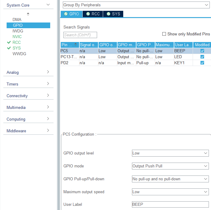
KEY1 is connected to the PD2 pin. Set PD2 to GPIO_Input mode and change the Label to KEY1. Other configurations are shown in the following figure.

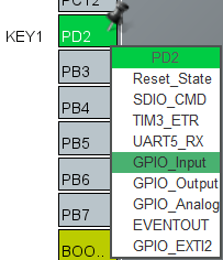
Save and generate the code.
3.3. Analysis of experimental flow chart
3.4. Add file structure
By configuring the pin information graphically, the generated code already contains the system initialization content, so there is no additional need to initialize the system configuration.
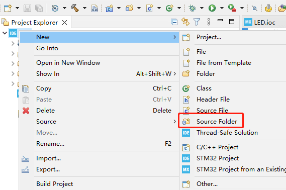
For easy management, we create a new BSP source folder. Right-click ->New->Source Folder over the mouse move project name
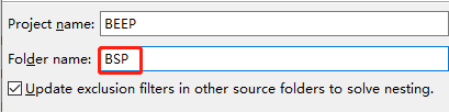
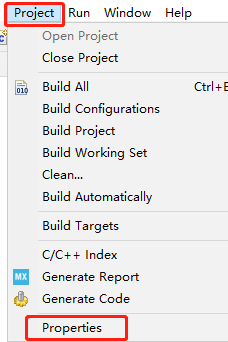
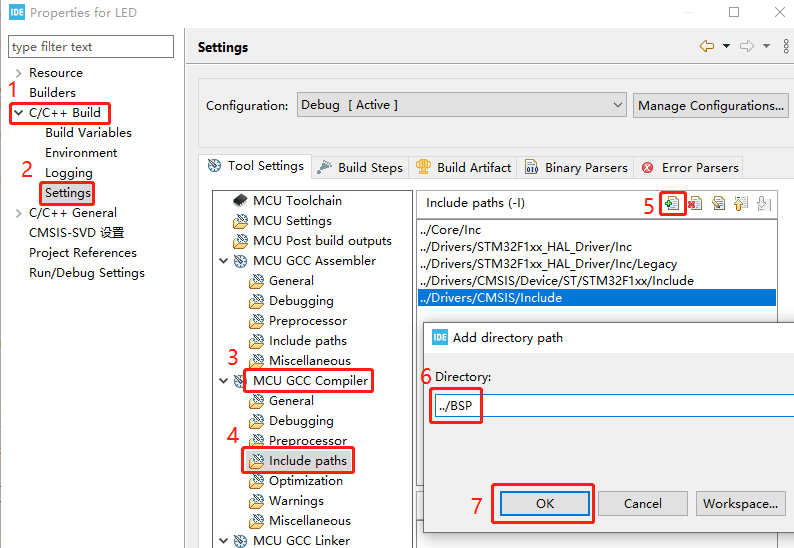
Add the BSP to the environment. Click Project->Properties->C/C++ Build->settings->MCU GCC Compiler->include paths, and then click Add button to.../BSP fill in and save.
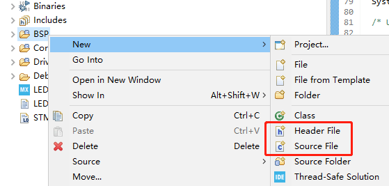
Create a bsp.h and a bsp.c File, right-click BSP->New->Header File/Source File, and enter the corresponding name.
These two files are mainly responsible for linking some functions in main.c, which can avoid repeated code writing.
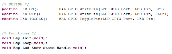
Add the following content in bsp.h: Make the LED control into a macro definition, simple and fast.The new Bsp_Init() function is mainly responsible for initialization, and Bsp_Loop() is mainly responsible for the main program content.The Bsp_Led_Show_State_Handle() function is mainly responsible for the LED flashing effect, which is used to indicate that the system is running.
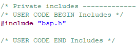
Import the bsp.h header file to main.c.
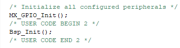
Call Bsp_Init() from the main function.
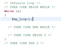
Call Bsp_Loop() in while(1).
3.5. Core code interpretation
Create the bsp_beep.h and bsp_beep.c driver libraries of the buzzer in the BSP. Add the following to bsp_beep.h:

The Beep_Timeout_Close_Handle() function needs to be called every 10ms to ensure that the Beep_On_Time() function works normally after setting the time. Beep_On_Time(time) indicates the time when the buzzer is enabled. If time=0, the buzzer is turned off. If time=1, the buzzer keeps ringing. If time>=10, the buzzer is turned off automatically in milliseconds.
Create the bsp_key.h and bsp_key.c files of the buzzer driver library in the BSP. Add the following to bsp_key.h:
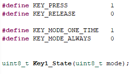
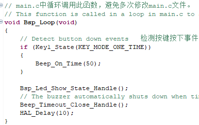
The Key1_State(mode) function is used to detect whether the key is pressed, and it needs to be called every 10 milliseconds. mode can be entered 0 or 1, mode=0 means that when KEY1 is pressed, KEY_PRESS will always be returned, and KEY_RELEASE will be returned when KEY1 is released. mode=1 means that no matter how long KEY1 is pressed, KEY_PRESS will only be returned once, and KEY_RELEASE will be returned in other cases.
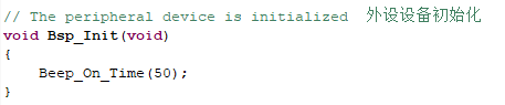
In Bsp_Init(), add the power buzzer to ring for 50 milliseconds. In Bsp_Loop(), check whether the key is pressed. At the bottom is the control handle for the LED lights and buzzers, which only need to be called every 10 milliseconds.
3.6. Hardware connection
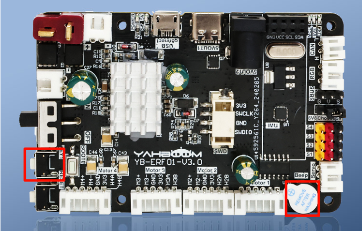
The KEY1 and buzzer are both on-board components and do not require manual connection.
3.7. Experimental effect
After the program is burned, the buzzer will ring for 50 milliseconds when it is turned on, the LED light will flash every 200 milliseconds, and the buzzer will ring for 50 milliseconds every time the key is pressed.