Welcome to RDK X5 Robot repository
11. Nine-axis attitude sensor to obtain data
11. Nine-axis attitude sensor acquisition data -ICM20948
11. Nine-axis attitude sensor acquisition data -ICM2094811.1. Experimental purpose11.2. Configure pin information11.3. Analysis of experimental flow chart11.4. Core code interpretation11.5. Hardware connection11.6. Experimental effect
11.1. Experimental purpose
Using the SPI communication of STM32, the original data of the nine-axis attitude sensor ICM20948 is read and printed out through the serial assistant.
11.2. Configure pin information
- Import the ioc file from the Serial project and name it Read_ICM20948.
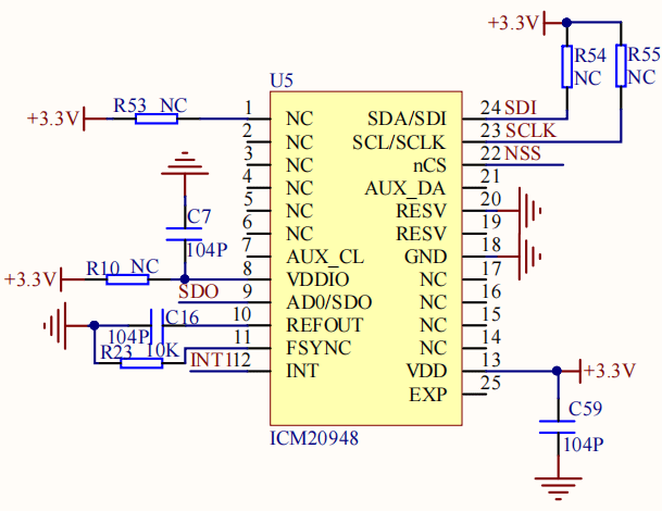
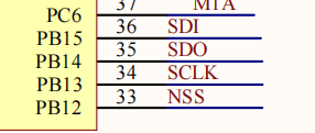
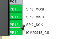
According to the schematic diagram, the SDA/SDI pin of the nine-axis attitude sensor is connected to PB15, the SCL/SCLK pin is connected to PB13, the AD0/SDO pin is connected to PB14, and the NSS pin is connected to PB12.
- Enable SPI2 interface, set PB13, PB14 and PB15 as SPI2 pins, and use PB12 software to control NSS chip selection pins. Specific parameters are shown in the figure below:
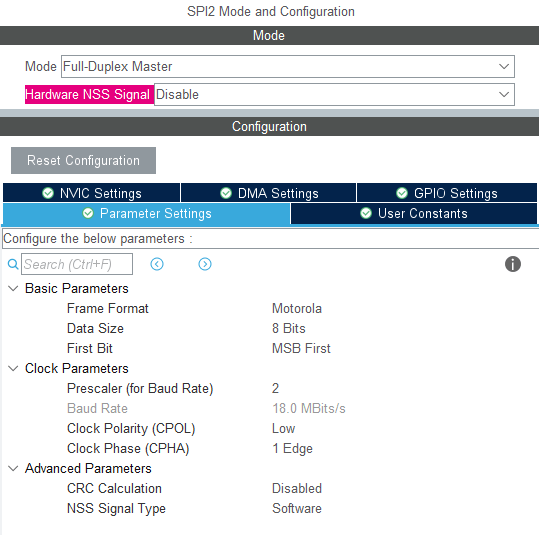
Then set PB12 to output mode and rename it ICM20948_CS
11.3. Analysis of experimental flow chart
11.4. Core code interpretation
- Create bSP_ICM209448.h and bsp_ICM209448.c, and add the following content to bsp_ICM209448.h:
xxxxxxxxxxvoid ICM20948_init();void AK09916_init();// read raw data.void ICM20948_gyro_read(raw_data_t* data);void ICM20948_accel_read(raw_data_t* data);bool AK09916_mag_read(raw_data_t* data);// Convert 16 bits ADC value to their unit.void ICM20948_gyro_read_dps(axises_t* data);void ICM20948_accel_read_g(axises_t* data);bool AK09916_mag_read_uT(axises_t* data);bool ICM20948_who_am_i();bool AK09916_who_am_i();void ICM20948_Read_Data_Handle(void);
- Create the following content in the bsp_icm20948.c file:
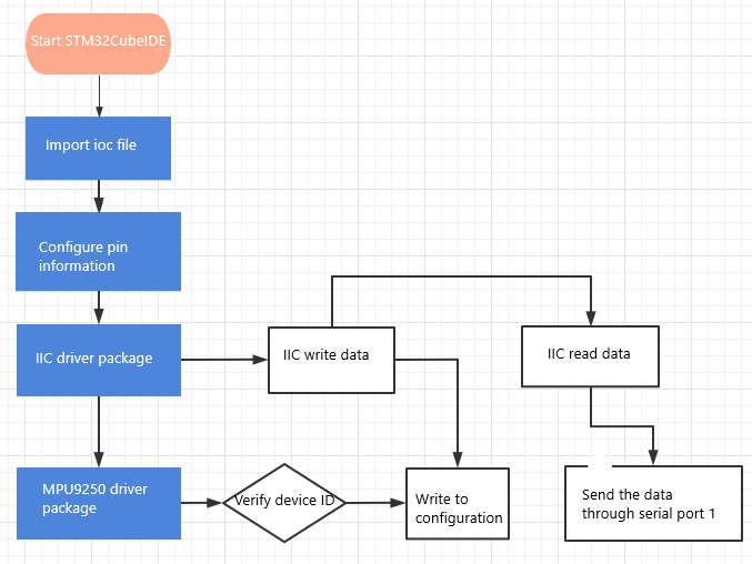
Start initializing the ICM20948 by resetting and waking up the ICM20948, setting the clock source, magnetometer access, and filtering, then calibrating the gyroscope and accelerometer, and setting the scaling ratio.
xxxxxxxxxxvoid ICM20948_init(){while(!ICM20948_who_am_i());ICM20948_device_reset();ICM20948_wakeup();ICM20948_clock_source(1);ICM20948_odr_align_enable();ICM20948_spi_slave_enable();ICM20948_gyro_low_pass_filter(0);ICM20948_accel_low_pass_filter(0);ICM20948_gyro_sample_rate_divider(0);ICM20948_accel_sample_rate_divider(0);ICM20948_gyro_calibration();ICM20948_accel_calibration();ICM20948_gyro_full_scale_select(_2000dps);ICM20948_accel_full_scale_select(_16g);}
- Initialize the AK09916 magnetometer.
xxxxxxxxxxvoid AK09916_init(){ICM20948_i2c_master_reset();ICM20948_i2c_master_enable();ICM20948_i2c_master_clk_frq(7);while(!AK09916_who_am_i());AK09916_soft_reset();AK09916_operation_mode_setting(continuous_measurement_100hz);}
- Enable and disable SPI communication for ICM20948.
xxxxxxxxxxstatic void ICM20948_NoActive(){HAL_GPIO_WritePin(ICM20948_CS_GPIO_Port, ICM20948_CS_Pin, SET);}static void ICM20948_Active(){HAL_GPIO_WritePin(ICM20948_CS_GPIO_Port, ICM20948_CS_Pin, RESET);}
- The method of SPI reading data, read_single_reg reads one byte of data from a register, read_multiple_reg reads multiple bytes of data from a register.
xxxxxxxxxxstatic uint8_t read_single_reg(userbank_t ub, uint8_t reg){uint8_t read_reg = READ | reg;uint8_t reg_val;select_user_bank(ub);ICM20948_Active();HAL_SPI_Transmit(ICM20948_SPI, &read_reg, 1, 1000);HAL_SPI_Receive(ICM20948_SPI, ®_val, 1, 1000);ICM20948_NoActive();return reg_val;}static uint8_t* read_multiple_reg(userbank_t ub, uint8_t reg, uint8_t len){uint8_t read_reg = READ | reg;static uint8_t reg_val[6];select_user_bank(ub);ICM20948_Active();HAL_SPI_Transmit(ICM20948_SPI, &read_reg, 1, 1000);HAL_SPI_Receive(ICM20948_SPI, reg_val, len, 1000);ICM20948_NoActive();return reg_val;}
6.SPI writes data. write_single_reg writes one byte of data to a register, and write_multiple_reg writes multiple bytes of data to a register.
xxxxxxxxxxstatic void write_single_reg(userbank_t ub, uint8_t reg, uint8_t val){uint8_t write_reg[2];write_reg[0] = WRITE | reg;write_reg[1] = val;select_user_bank(ub);ICM20948_Active();HAL_SPI_Transmit(ICM20948_SPI, write_reg, 2, 1000);ICM20948_NoActive();}static void write_multiple_reg(userbank_t ub, uint8_t reg, uint8_t* val, uint8_t len){uint8_t write_reg = WRITE | reg;select_user_bank(ub);ICM20948_Active();HAL_SPI_Transmit(ICM20948_SPI, &write_reg, 1, 1000);HAL_SPI_Transmit(ICM20948_SPI, val, len, 1000);ICM20948_NoActive();}
- Read the original accelerometer data. Since the calibration function cancels out the acceleration of gravity, the scale factor is added to the Z-axis to restore the reading value to normal.
xxxxxxxxxxvoid ICM20948_accel_read(raw_data_t* data){uint8_t* temp = read_multiple_reg(ub_0, B0_ACCEL_XOUT_H, 6);data->x = (int16_t)(temp[0] << 8 | temp[1]);data->y = (int16_t)(temp[2] << 8 | temp[3]);// data->z = (int16_t)(temp[4] << 8 | temp[5]);data->z = (int16_t)(temp[4] << 8 | temp[5]) + g_scale_accel;// Add scale factor because calibraiton function offset gravity acceleration.}
The raw accelerometer data and scale factor are combined to convert the unit to g.
xxxxxxxxxxvoid ICM20948_accel_read_g(axises_t* data){ICM20948_accel_read(&g_raw_accel);data->x = (float)(g_raw_accel.x / g_scale_accel);data->y = (float)(g_raw_accel.y / g_scale_accel);data->z = (float)(g_raw_accel.z / g_scale_accel);}
- Read the original gyroscope data.
xxxxxxxxxxvoid ICM20948_gyro_read(raw_data_t* data){uint8_t* temp = read_multiple_reg(ub_0, B0_GYRO_XOUT_H, 6);data->x = (int16_t)(temp[0] << 8 | temp[1]);data->y = (int16_t)(temp[2] << 8 | temp[3]);data->z = (int16_t)(temp[4] << 8 | temp[5]);}
The raw gyroscope data and scale factor are combined to convert the unit to dps.
xxxxxxxxxxvoid ICM20948_gyro_read_dps(axises_t* data){ICM20948_gyro_read(&g_raw_gyro);data->x = (float)(g_raw_gyro.x / g_scale_gyro);data->y = (float)(g_raw_gyro.y / g_scale_gyro);data->z = (float)(g_raw_gyro.z / g_scale_gyro);}
- Read the magnetometer raw data.
xxxxxxxxxxbool AK09916_mag_read(raw_data_t* data){uint8_t* temp;uint8_t drdy, hofl;drdy = read_single_mag_reg(MAG_ST1) & 0x01;if(!drdy) return false;temp = read_multiple_mag_reg(MAG_HXL, 6);hofl = read_single_mag_reg(MAG_ST2) & 0x08;if(hofl) return false;data->x = (int16_t)(temp[1] << 8 | temp[0]);data->y = (int16_t)(temp[3] << 8 | temp[2]);data->z = (int16_t)(temp[5] << 8 | temp[4]);return true;}
Convert the original magnetometer data into uT.
xxxxxxxxxxbool AK09916_mag_read_uT(axises_t* data){bool new_data = AK09916_mag_read(&g_raw_mag);if(!new_data) return false;data->x = (float)(g_raw_mag.x * 0.15);data->y = (float)(g_raw_mag.y * 0.15);data->z = (float)(g_raw_mag.z * 0.15);return true;}
- Add the content to initialize ICM20948 and AK09916 in the Bsp_Init() function.
xxxxxxxxxxvoid Bsp_Init(void){USART1_Init();ICM20948_init();AK09916_init();Beep_On_Time(50);}
- Add the ability to read ICM20948 data to the Bsp_Loop() function.
xxxxxxxxxxvoid Bsp_Loop(void){// Detect button down eventsif (Key1_State(KEY_MODE_ONE_TIME)){Beep_On_Time(50);static int press = 0;press++;printf("press:%d\n", press);}ICM20948_Read_Data_Handle();Bsp_Led_Show_State_Handle();// The buzzer automatically shuts down when times outBeep_Timeout_Close_Handle();HAL_Delay(10);}
11.5. Hardware connection
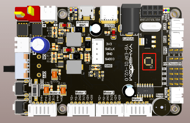
The ICM20948 nine-axis attitude sensor is already soldered to the expansion plate, so no manual device connection is required.
11.6. Experimental effect
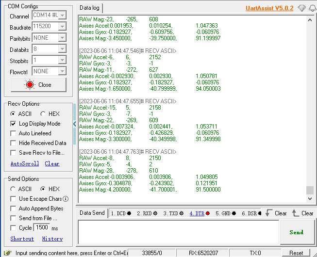
After burning the program, the LED light flashes every 200 milliseconds. Open the serial assistant (parameters are shown below), you can see that the serial assistant has been printing the accelerometer accel, gyroscope gyro, magnetometer mag data of ICM20948.