Welcome to RDK X5 Robot repository
14. Theory of robot kinematics analysis
14. Robot kinematics analysis theory
Kinematic analysis of Mecanum wheel
14. Robot kinematics analysis theoryKinematic analysis of Mecanum wheel14.1. Introduction to Mecanum Wheel14.2. Motion analysis and direction determination of Mecanum wheel14.3. Mecanum wheel mounting combination and motion analysis14.4. Installation location of Mecanum wheel14.5. Final installation method
14.1. Introduction to Mecanum Wheel
In the flourishing era of industrial manufacturing, people feel that the steering of traditional vehicles is very inconvenient to use in some specific environments, such as the assembly of components in the aerospace field, the use of traditional vehicles to carry assembly will consume a lot of manpower, material resources and time. In the case of accuracy to a few tenths of a millimeter, it can only be recalibrated if it is inaccurate. For sophisticated, large equipment, high efficiency means that you can beat your rivals by a few blocks. If you can find a way for the vehicle to translate and rotate at any Angle without turning the body, you can solve this problem perfectly.
Until 1973, the Swedish company Mecanum developed a more practical solution that was widely adopted, and we will introduce the Mecanum wheel today.
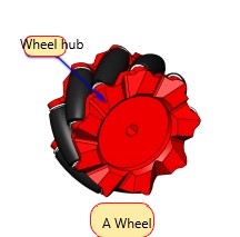
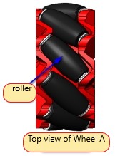
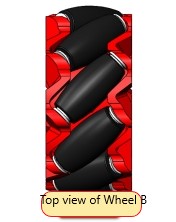
Mecanum wheel (hereinafter referred to as wheat wheel) is composed of the hub and the roller around the hub, the roller is A no power driven small roller, Mecanum wheel axis and hub axis Angle is 45 degrees, and there are two kinds of mutual mirror relationship A, B wheel, or will be called left wheel and right wheel. This is usually marked A and B, L and R above the hub.

14.2. Motion analysis and direction determination of Mecanum wheel
As mentioned above, there are two kinds of wheat wheel AB. If wheel A moves to the right at the same time when it moves forward, that is, it moves diagonally to the right and forward, then on the contrary, Wheel A moves backwards while it moves to the left, that is, it moves diagonally to the left and backward. The corresponding B wheel can be tilted left front and right rear.
With the head of the car as the positive direction, it is agreed that the direction of the wheel forward is the motor forward, and the direction of the wheel backward is the motor reverse. (All the following courses are explained in this direction)
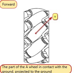
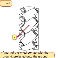
Take wheel A for example, the roller cannot provide forward force due to rolling in the moving direction of the roller, and the roller cannot roll in the direction of the roller axis and friction with the ground generates the friction of the roller axis, that is, the direction of the speed of wheel A is oblique to the right front or left back. The same can be said for series B.
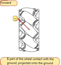
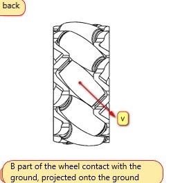
Based on the physics we learned in high school, we know that velocity can be decomposed orthogonally, and that the motion of the body depends on the combined velocity direction of the four wheels.
Then wheel A can be broken down into the axial right and vertical forward velocity components, or the axial left and vertical backward velocity components.
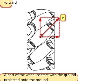
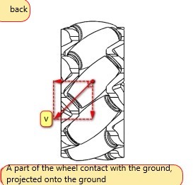
In this way, the velocity components of round B and round A are mirror images of each other.
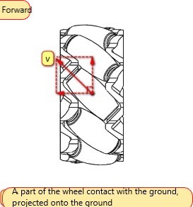
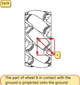
14.3. Mecanum wheel mounting combination and motion analysis
After knowing the speed component of the AB wheel, we can arrange and combine the chassis of the four-wheel Mecanum wheel: AAAA, BBBB, AABB...
Are all combinations capable of moving in all directions? Not really.
Let's take just one wrong example and one right example, the rest can be reasoned out (which is actually too many).
Analysis error example [AAAA]
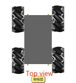
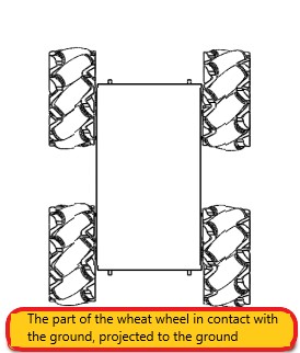
This doesn't look very good at first glance, but let's analyze it anyway, because as an example of a mistake, it's pretty easy to figure out what's wrong with it. We said earlier that the velocity component of round A is either front plus right or back plus left.
When the four wheels turn forward at the same time, each wheel will have a left speed component, which will cause the whole chassis to move to the left at the same time; In the same way, when you go backwards, you have to go to the right, so you can't use it, and this thing is running around uncontrollably, which is not the omnidirectional movement that we want.
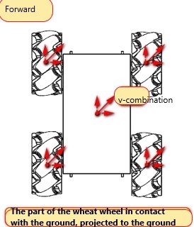
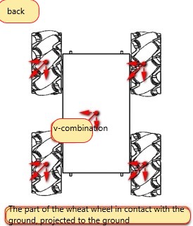
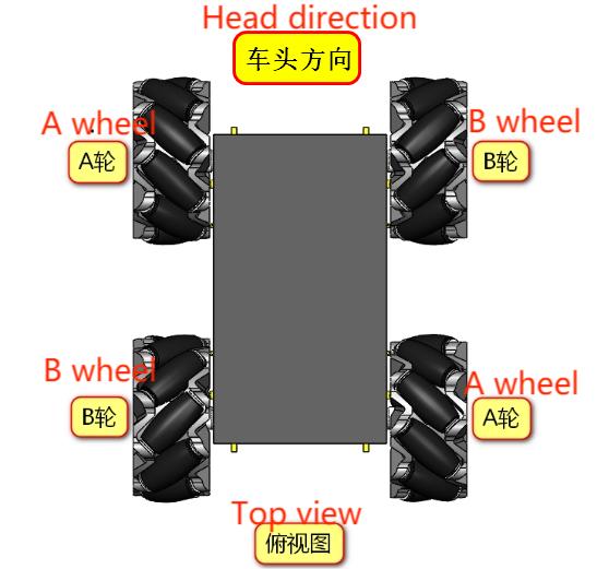
The correct wheatwheel distribution should be [ABBA]
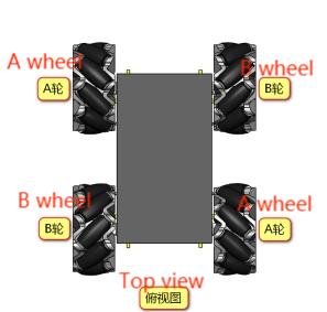
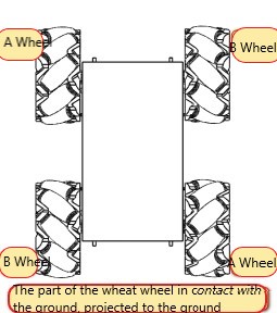
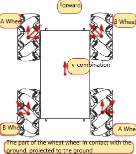
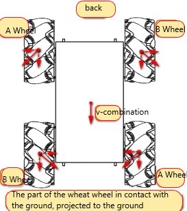
When the four wheels are turned forward, the AB wheel can offset each other's axial speed, leaving only the forward speed, so that the chassis is straight forward, will not run off, backward the same;
If when wheel A is turning forward and wheel B is reversing, the forward and backward speed will cancel out, leaving only the speed to the right, then the chassis will shift to the right;
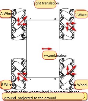
Conversely, if round A is reversed and round B is turned forward, it will shift to the left;

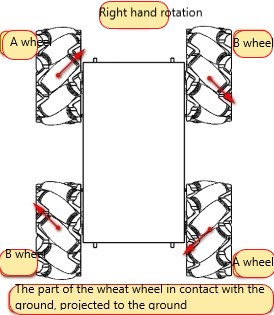
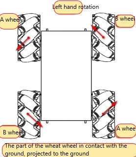
Finally, the left wheel of the chassis is turned forward and the right wheel is reversed to realize the right rotation; If not, the chassis will rotate to the left.
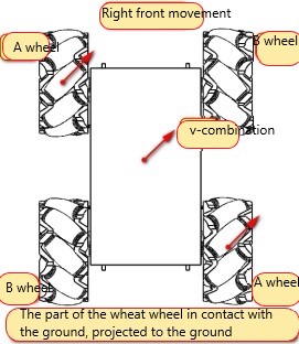
In addition, when the A wheel is turning and the B wheel is not moving, the chassis will move to the right front;
When the A wheel is reversed and the B wheel is not moving, the chassis moves left and rear.
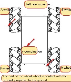
Accordingly, wheel A does not move, wheel B is turning, and the chassis moves to the left front;
The A wheel is stationary, the B wheel is reversed, and the chassis is moving to the right and rear.
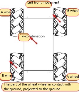
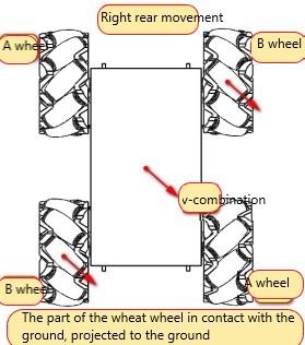
There are four other modes of movement that rotate around the midpoint of the axis.

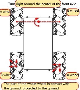
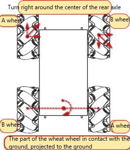
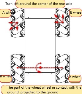
[Think] The above four cases are similar to translation, when the two stationary wheels move like translation, but the speed is less than the speed of the other two wheels, how will the wheat wheel chassis move?
14.4. Installation location of Mecanum wheel
In front of us, we have explained the installation combination of wheat wheels, and the location of the installation of four wheat wheels is also particular.
The shapes formed by the contact points between the four wheels and the ground are mainly square and rectangular. Strange shapes are not excluded, but only squares and rectangles are analyzed here.
Square: The four wheels are located at the four vertices of the square, translating and rotating without any problems. Limited by the shape, size and other factors of the robot chassis, this installation method is ideal, but it can not be sought.
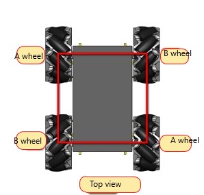
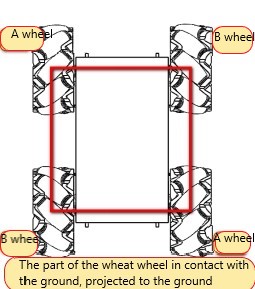
The chassis we use after the wheat wheel is carefully designed square, is the most ideal wheat wheel chassis.
Rectangular: The wheel rotation can produce Yaw axis rotation torque, and the torque arm is relatively long. Is the most common installation method.
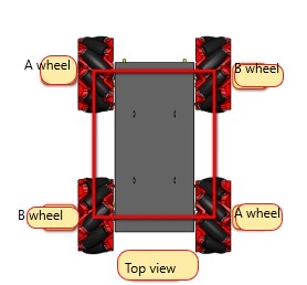
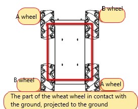
By comparing with traditional vehicles, we can find that the wheels of ordinary vehicles turn in the same direction when moving, while the vehicles using wheat wheels move in the same direction as the above analysis, each wheat wheel has a different direction of movement. Therefore, if the wheat wheel wants to achieve true omnidirectional movement, each wheat wheel needs a separate motor to drive. You also need a control system to control the steering and speed of each wheel.
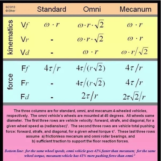
To achieve omnidirectional movement, omnidirectional wheel and Mecanum wheel are generally used. Above, we mainly introduce the movement mode and installation combination of wheat wheel. There are differences in structure, mechanics and kinematics between omnidirectional wheel and wheatwheel, the essential reason is that the Angle between hub shaft and roller shaft is different. After analysis, the kinematic and mechanical characteristics of the two can be reflected in the following table.
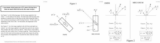
The calculation process is as follows, for reference only:
14.5. Final installation method