Welcome to RDK X5 Robot repository
6. Robot trajectory tracking
6. Robot trajectory tracking
6. Robot trajectory tracking6.1. Program function description6.2. Principle introduction6.3. Program code reference path6.4. Program startup
6.1. Program function description
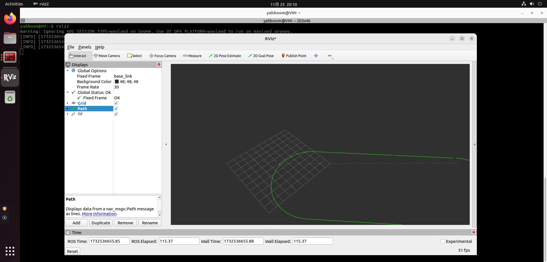
After the program is run, the car will run according to the trajectory given in the .csv file. Starting rviz on the virtual machine can realize the visualization of trajectory tracking.
In addition, the [L1] key of the handle can lock/open the motion control of the car. When the motion control is turned on, the function will be locked; when the motion control is locked, the function can be turned on.
6.2. Principle introduction
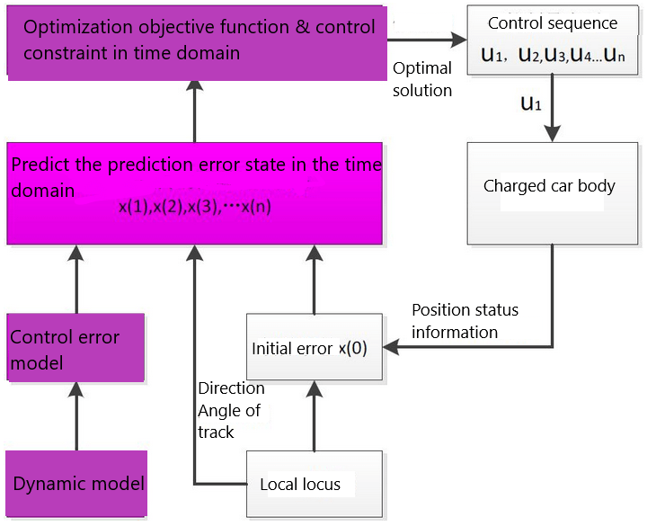
PurePuesuit and MPC algorithms are commonly used control algorithms in autonomous driving. The purpose is to make the trajectory points at the planning location smoother and meet the kinematic trajectory of the vehicle itself.
Before talking about the implementation of the two algorithms, it is necessary to understand that the two mainstream trajectory tracking algorithms are now divided into geometry-based tracking and model-based tracking methods.
In this implementation, it can basically be regarded as known coordinate information, including (x, y, yaw) and curvature Kappa, and the control amount steering angle, that is, the lateral motion, is calculated, so that the car can run smoothly within the trajectory.
Taking MPC as an example, the diagram is as follows:
PurePursuit
The pure tracking algorithm proposes the concept of "preview distance". According to the preview distance, it finds the target path point that meets the conditions in the target trajectory. The judgment logic is to find which point on the target trajectory has a relative distance equal to the current vehicle position equal to the preview distance, and this point is the target point at the current moment. The control goal is to calculate how large the front wheel deflection angle can make the current car position move to the target position. On this basis, let's take a brief look at the core point, what is the preview distance.
Simply put, the preview distance is like finding a tracking reference point when driving. For example, when driving on a straight road, we will choose a higher speed and are used to considering a point farther ahead as a tracking reference point; when driving on a curve, we will choose to slow down and are used to choosing a closer point as a tracking reference point. So this value is a value that we can set ourselves. The setting of this value will also greatly affect the movement of the car. For example, in the findCloestindex function in the code of this example, we found the nearest point based on the preview distance:
//Formula: ld=l+kvld=l+kv (too dependent on the selection of the foresight distance, you can use the dynamic foresight distanceld=l+kvld=l+kvwhere l, kl, and k are coefficients, and the foresight distance is adjusted according to the speed)double ld = kv*linear_x+ld0;double ld_now = 0;while(ld_now<ld && index<=(int)xr.size()) {double dx_ref = xr[index+1] - xr[index];double dy_ref = yr[index+1] - yr[index];ld_now += sqrt(pow(dx_ref,2)+pow(dy_ref,2));index++;}After obtaining this point, calculate the turning angle according to the model limit of the car itself:
xxxxxxxxxxdouble PurePursuit::calSteeringAngle(double alpha,double ld){double steer = atan2(2*track*sin(alpha),ld);if (steer > M_PI) {steer -= M_PI*2;} else if (steer < (-M_PI)) {steer += M_PI*2;}return steer;}MPC
The solution of MPC is relatively more complicated. Directly show the code framework:
Get the body parameters.
Select the state and control quantities.
Discretize the AB matrix, and add the perturbation matrix in Apollo.
Set the QR matrix.
Set the number of prediction steps and augment ABQR.
Set the constraints of relevant parameters and obtain the values of each sensor.
Solve the control quantity u and finally get u[0].
For more specific logic, please refer to this link: https://blog.csdn.net/u013914471/article/details/83824490
6.3. Program code reference path
After SSH connects to the car, the source code of this function is located at,
xxxxxxxxxx#Purepursuit/home/sunrise/yahboomcar_ws/src/yahboomcar_autonomous/Purepursuit/src/purepursuit.cc#MPC/home/sunrise/yahboomcar_ws/src/yahboomcar_autonomous/MPC/launch/yahboomcar_mpc.launch.pyAmong them, the .csv file of the trajectory is located at,
xxxxxxxxxx/home/sunrise/yahboomcar_ws/src/yahboomcar_autonomous/waypoints/path.csv6.4. Program startup
After SSH connects to the car, enter in the terminal,
xxxxxxxxxx#Start chassisros2 launch yahboomcar_bringup yahboomcar_bringup_launch.py#Purepursuitros2 run yahboomcar_autonomous purepursuit_node#MPCros2 launch yahboomcar_autonomous yahboomcar_mpc.launch.pyVirtual machine input,
xxxxxxxxxxrviz2