Welcome to MSPM0 Smart Robot Car repository
3. Button Control (EXTI)
Button Control
Button ControlI. Learning ObjectivesII. External Interrupt IntroductionIII. Hardware SetupIII. Experiment Steps1. Open SYSCONFIG Configuration Tool2. Parameter Settings2.1 Set Port Parameters2.3 Save and Update Configuration File3. Write Program4. CompileIV. Program AnalysisV. Experiment Phenomenon
I. Learning Objectives
- Learn the basic usage of MSPM0G3507 development board pins.
- Understand how to control the onboard button.
II. External Interrupt Introduction
An interrupt is when the CPU is executing a program and another event needs to occupy the CPU. After receiving this interrupt request, the CPU pauses the execution of the original program, executes the interrupt function, and after the interrupt function execution is completed, returns to the original program to continue execution.
External Interrupt refers to an interrupt triggered by external hardware events (usually signals from outside the microcontroller). This interrupt can interrupt the current program execution flow of the microcontroller, thereby quickly responding to external hardware events.
The triggering of external interrupts is usually associated with specific pins (GPIO pins), such as buttons, sensor signals, timer signals, etc. These pins are typically configured to detect specific signal changes (such as rising edge, falling edge, or level changes) to trigger interrupts.
Advantages and Functions of External Interrupts
Advantages:
- Fast response: External interrupts can respond immediately when a trigger event occurs, without needing to poll the signal.
- Resource saving: No need to continuously detect signal status in the main loop, saving CPU resources.
- Improved real-time performance: The interrupt mechanism ensures timely processing of key events, thereby improving system real-time performance.
Functions:
- Quick response to external events: Can immediately interrupt current program execution when a hardware event occurs and quickly process the event, without needing to poll and check signal status. This avoids program polling of events, greatly saves CPU resources, and improves the system's response speed to external events.
- Improve system real-time performance: In scenarios requiring real-time response, external interrupts can ensure key events are processed in a timely manner, without waiting for the system's main program to complete current tasks, thereby improving system real-time performance.
- Reduce main program burden: External interrupts can separate tasks related to external events from the main program, avoiding polling signal status checks in the main program, improving main program execution efficiency, and allowing the main program to focus on core tasks.
- Core of event-driven systems: Can achieve efficient event-driven mechanisms, reducing system complexity.
- Implement hardware interaction and control: External interrupts enable microcontrollers to process and respond to external hardware signals in real-time, ensuring normal system operation.
- Data acquisition and processing: In many real-time data acquisition systems, external interrupts are used to trigger data acquisition or processing.
- Trigger mechanism for low-power scenarios: Through external interrupts, efficient low-power design can be achieved, keeping the system in sleep state when not working, only running when necessary.
- Ensure system safety: Timely processing of safety-related events ensures system reliability and security.
III. Hardware Setup
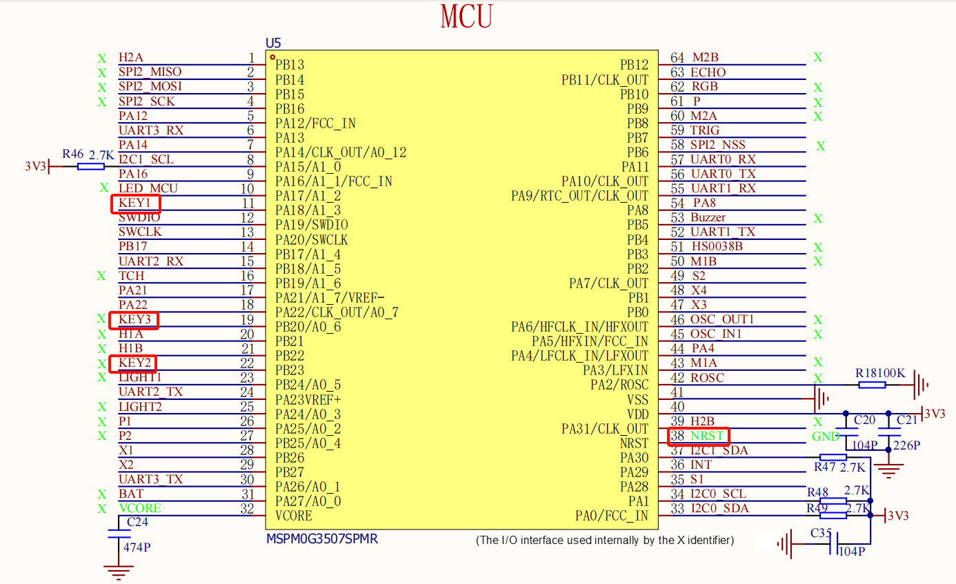
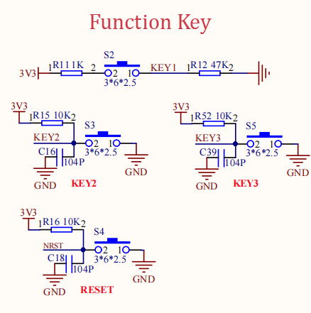
This course requires no additional hardware devices, directly using the onboard button on the MSPM0G3507 development board.
MSPM0G3507 Main Control Diagram
Button Part Circuit Diagram
III. Experiment Steps
1. Open SYSCONFIG Configuration Tool
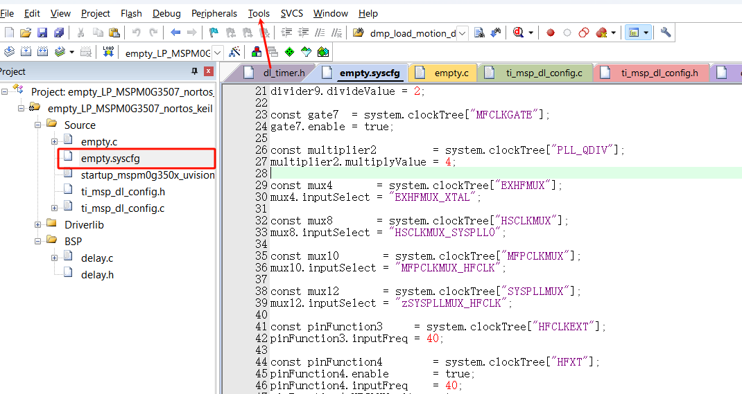
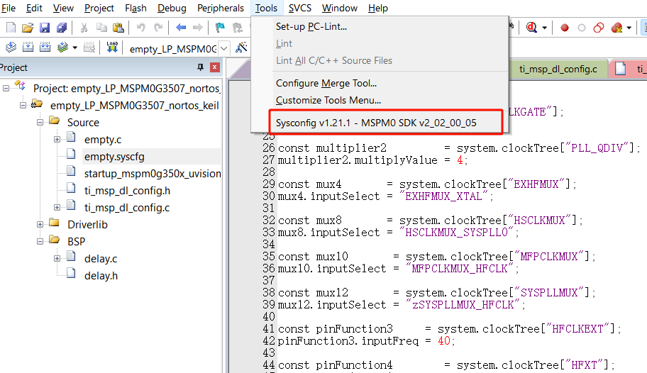
In KEIL, open the empty project from the SDK. After selecting and opening, in the KEIL interface, open the empty.syscfg file. With the empty.syscfg file open, select Open SYSCONFIG GUI interface from the Tools menu.
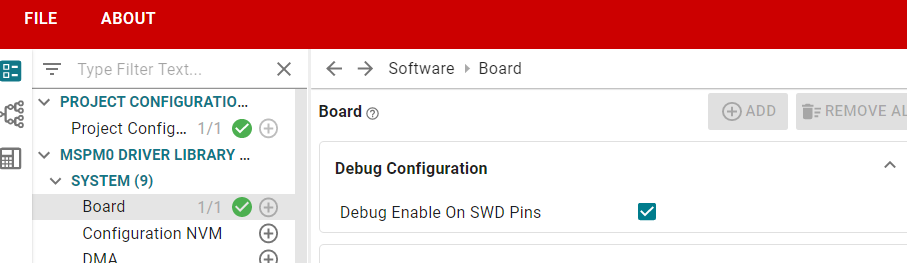
We first enable SWD debugging so that we can use debugging tools (DAP-Link, Jlink) to burn and debug the project.
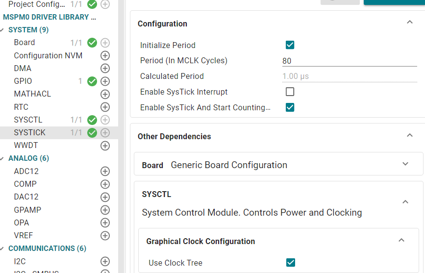
We need to enable the SYSTICK clock for delay, set it to 1us here. Whether to enable SYSTICK interrupt depends on needs, it is disabled by default here (the period can be adjusted according to the clock tree configuration).
2. Parameter Settings
2.1 Set Port Parameters
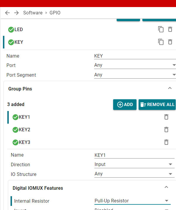
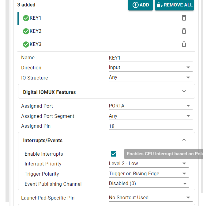
In SYSCONFIG, select MCU peripherals on the left, find GPIO option and click to enter. In GPIO, click ADD to add a GPIO group, the name can be customized, here it is KEY.
Set GPIO parameters, name these pins as KEY1, KEY2, KEY3, where KEY1 is set as external interrupt input
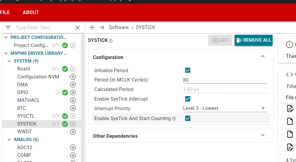
In this section, we use systick interrupt for timing
Enable external interrupt
2.3 Save and Update Configuration File
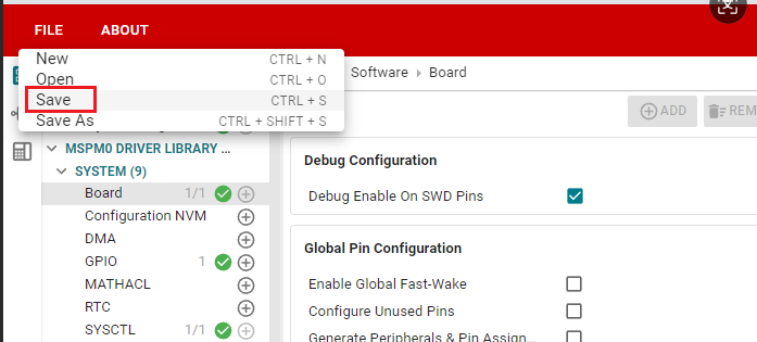
Click SAVE to save the configuration in SYSCONFIG, then close SYSCONFIG and return to keil.
Select Yes to All in the pop-up window
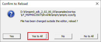
After that, we can see that the empty.syscfg file has been updated with our set parameters.
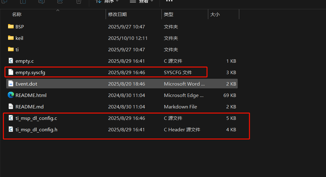
We also need to confirm whether ti_msp_dl_config.c and ti_msp_dl_config.h files are updated. Directly compile, compilation will automatically update to keil. If not updated, we manually select the project path to save
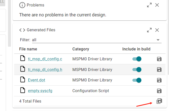
Relative path as follows
3. Write Program
In the empty.c file, write the following code
xxxxxxxxxx#include "ti_msp_dl_config.h"#include "KEY.h"int main(void){ // Initialize system configuration //Enable GPIOA port interrupt for button pins SYSCFG_DL_init(); NVIC_EnableIRQ(KEY_INT_IRQN); while (1) { // Detect KEY2 (toggle LED when pressed) if (KEY2_IsPressed()) { LED_Toggle(); delay_ms(200); // Debounce while (KEY2_IsPressed()); // Wait for release // Detect KEY3 (toggle LED when pressed) if (KEY3_IsPressed()) { LED_Toggle(); delay_ms(200); // Debounce while (KEY3_IsPressed()); // Wait for release } }}KEY.c
xxxxxxxxxx// Detect KEY1 (pull-down, high level when pressed) uint8_t KEY1_IsPressed(void){ return DL_GPIO_readPins(KEY_KEY1_PORT, KEY_KEY1_PIN) == KEY_KEY1_PIN;}// Detect KEY2 (pull-up, low level when pressed)uint8_t KEY2_IsPressed(void){ return DL_GPIO_readPins(KEY_KEY2_PORT, KEY_KEY2_PIN) != KEY_KEY2_PIN;}// Detect KEY3 (pull-up, low level when pressed) uint8_t KEY3_IsPressed(void){ return DL_GPIO_readPins(KEY_KEY3_PORT, KEY_KEY3_PIN) != KEY_KEY3_PIN; }// Toggle LED status void LED_Toggle(void){ DL_GPIO_togglePins(LED_PORT, LED_MCU_PIN);}void GROUP1_IRQHandler(void)//Interrupt service function for Group1{ //Read Group1 interrupt register and clear interrupt flag switch( DL_Interrupt_getPendingGroup(DL_INTERRUPT_GROUP_1) ) { //Check if it is KEY GPIOA port interrupt, note it's INT_IIDX, not PIN_18_IIDX case KEY_INT_IIDX: if( DL_GPIO_readPins(KEY_KEY1_PORT, KEY_KEY1_PIN) > 0 ) { for (int j = 0; j < 80000; j++) { // Only execute a simple operation that can predict its execution time // "nop" represents "no operation", which consumes one or several clock cycles in most architectures, not fixed __asm__("nop"); } //If button pressed becomes low level if( DL_GPIO_readPins(KEY_KEY1_PORT, KEY_KEY1_PIN) > 0 ) { //Set LED pin status toggle LED_Toggle(); } } break; }}delay.c
xxxxxxxxxx//Using method 0, 1 to implement delay requires disabling systick interrupt //The following implements delay using three methods: 0: using a loop of no operations to implement delay 1: using polling to read systick count to implement delay 2: using systick interrupt to implement delay (default) If using the first two methods, disable systick interrupt volatile unsigned int delay_times = 0;//自定义延时(不精确) Custom delay (not precise)void delay_ms(unsigned int ms){ unsigned int i, j; // The number of nested loops below is roughly calculated based on the main control frequency and the instruction cycle generated by the compiler, // and needs to be adjusted through actual testing to achieve the required delay. for (i = 0; i < ms; i++) { for (j = 0; j < 8000; j++) { // Only execute a simple operation that can predict its execution time // "nop" represents "no operation", which consumes one or several clock cycles in most architectures, not fixed __asm__("nop"); } }}//Implement delay by polling systick count void delay_us(unsigned long __us) { uint32_t ticks; uint32_t told, tnow, tcnt = 0; ticks = __us * (80000000 / 1000000); told = SysTick->VAL; while (1) { tnow = SysTick->VAL; if (tnow != told) { if (tnow < told) tcnt += told - tnow; else tcnt += (SysTick->LOAD + 1) - tnow + told; told = tnow; if (tcnt >= ticks) break; } }}//Precise ms delay implemented with tick timervoid delay_ms(unsigned long ms) { while (ms--) { delay_us(1000); }} //Implement delay using systick interrupt, need to enable systick interrupt in sysconfig void delay_ms(unsigned int ms){ delay_times=ms; while(delay_times!=0);}void SysTick_Handler(void){ if( delay_times != 0 ) { delay_times--; }}4. Compile
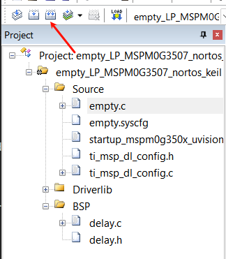
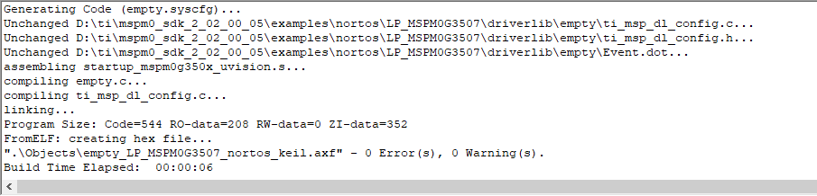
Click the Rebuild icon. The following prompt indicates that compilation is complete and there are no errors.
IV. Program Analysis
- dl_gpio.h
xxxxxxxxxx/** * @brief Set a group of GPIO pins * * @param[in] gpio Pointer to the register overlay for the peripheral * @param[in] pins Pins to set high. Bitwise OR of @ref DL_GPIO_PIN. */__STATIC_INLINE void DL_GPIO_setPins(GPIO_Regs* gpio, uint32_t pins){ gpio->DOUTSET31_0 = pins;}/** * @brief Clear a group of GPIO pins * * @param[in] gpio Pointer to the register overlay for the peripheral * @param[in] pins Pins to clear. Bitwise OR of @ref DL_GPIO_PIN. */__STATIC_INLINE void DL_GPIO_clearPins(GPIO_Regs* gpio, uint32_t pins){ gpio->DOUTCLR31_0 = pins;}/** * @brief Toggle a group of GPIO pins * * @param[in] gpio Pointer to the register overlay for the peripheral * @param[in] pins Pins to toggle. Bitwise OR of @ref DL_GPIO_PIN. */__STATIC_INLINE void DL_GPIO_togglePins(GPIO_Regs* gpio, uint32_t pins){ gpio->DOUTTGL31_0 = pins;}__STATIC_INLINE void DL_GPIO_setPins(GPIO_Regs* gpio, uint32_t pins): This function controls the pin to output high level.
__STATIC_INLINE void DL_GPIO_clearPins(GPIO_Regs* gpio, uint32_t pins): This function controls the pin to output low level.
__STATIC_INLINE void DL_GPIO_togglePins(GPIO_Regs* gpio, uint32_t pins): This function controls the pin level toggle, if it was high level it becomes low level, if it was low level it becomes high level.
V. Experiment Phenomenon
After the program download is complete, we can press any of KEY1, KEY2, KEY3 buttons to toggle the LED on/off