Welcome to MSPM0 Smart Robot Car repository
13.K230 vision recognition module
K230 Vision Recognition Module
K230 Vision Recognition Module1. Software and Hardware2. Basic Principles2.1 Hardware Schematic2.2 Physical Connection Diagram2.3 Control Principle3. Project Configuration3.1 Description3.2 Pin Configuration4. Main Functions4.1 User Functions5. Experimental Phenomenon
This tutorial demonstrates: how the MSPM0G3507 expansion board works with the K230 vision recognition module, using the function buttons on the expansion board to control the K230 module.
1. Software and Hardware
KEIL5
MSPM0G3507 Development Board
Function buttons integrated on the development board
K230 Vision Module
Type-C data cable or ST-Link
For programming download or simulation to the development board
Serial Port Assistant
Receive and print serial port data
2. Basic Principles
2.1 Hardware Schematic
.png)
2.2 Physical Connection Diagram
.png)
2.3 Control Principle
K230 Wiring (Note: The wiring diagram below is for position reference only. Our factory provides K230 dual-head PH2.0 4Pin all-black cables with anti-mistake design, so you don't need to worry about wiring issues)
| K230 | MSPM0G3507 |
|---|---|
| RX | TX2 |
| TX | RX2 |
| GND | GND |
| 5V | 5V |
Serial Communication:
USART: Universal Synchronous/Asynchronous Receiver/Transmitter. It is a hardware peripheral integrated inside MSPM0G3507 that can automatically generate data frame timing based on one byte of data from the data register and send it out through the TX pin, or automatically receive data frame timing from the RX pin and concatenate it into one byte of data, stored in the data register.
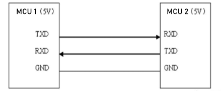
When using serial port for communication, both communication parties must be on the "same channel". "Same channel" means the same communication protocol. Serial port (USART) stipulates: data must be transmitted in the form of "frames" during communication. One frame of serial port data includes: start bit + data bit + parity bit + stop bit. Where: 1) Start bit: fixed is 1 cycle low level signal 2) Data bit: can be agreed by both parties as 5 ~ 9 bits 3) Parity bit: serial port uses parity check, can be agreed by both parties 4) Stop bit: optional 0.5 ~ 2 cycles high level. At the same time, to synchronize the transmission speed of both parties, it is also necessary to agree on the number of data frames transmitted per second, called baud rate. Typical baud rates include 9600, 115200, 57600...
K230 vision module function distribution is as follows:
To compress the module size, our K230 module does not bring out all pins supported by the chip. Let's look at some commonly used pins of YAHBOOM K230
Two rows of pins next to the heat sink
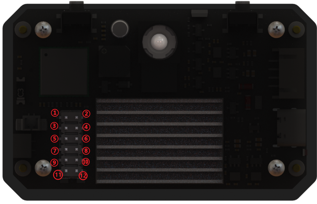
1 : GPIO 42, can be multiplexed as: GPIO42 / UART1_RTS / PWM0 / QSPI1_D2 / RESV /
2 : GPIO 43, can be multiplexed as: GPIO43 / UART1_CTS / PWM1 / QSPI1_D3 / RESV /
3 : GPIO 33, can be multiplexed as: GPIO33 / IIC0_SDA / IIS_WS / UART3_RXD / RESV /
4 : GND
5 : GPIO 32, can be multiplexed as: GPIO32 / IIC0_SCL / IIS_CLK / UART3_TXD / RESV /
6 : GPIO 26, can be multiplexed as: GPIO26 / MMC1_CLK / RESV / PDM_CLK /
7 : GND
8 : GPIO 34, can be multiplexed as: GPIO34 / IIC1_SCL / IIS_D_IN0 / PDM_IN3 / UART3_RTS /
9 : 5v output
10 : GPIO 35, can be multiplexed as: GPIO35 / IIC1_SDA / IIS_D_OUT0 / PDM_IN1 / UART3_CTS /
11 : 5v output
12 : 3.3v output
!!! When connecting 12pin GPIO, please be sure to confirm the silkscreen markings to ensure correct connection. Artificial damage caused by short circuit, reverse connection, overvoltage or overcurrent will not be able to provide after-sales repair service. !!!!
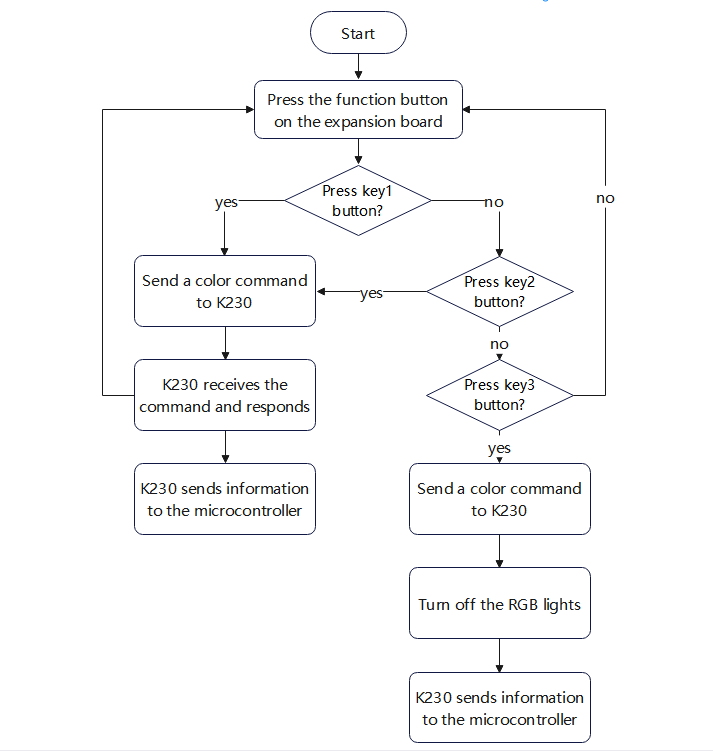
Operation flow chart is as follows:
3. Project Configuration
3.1 Description
You can refer to the basic tutorial to complete the development environment setup.
3.2 Pin Configuration
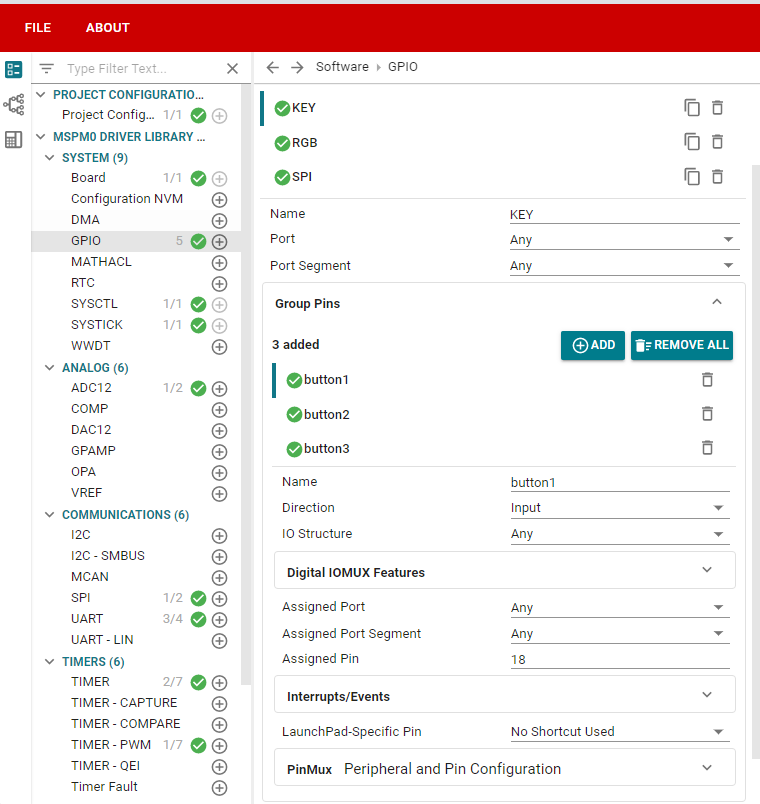
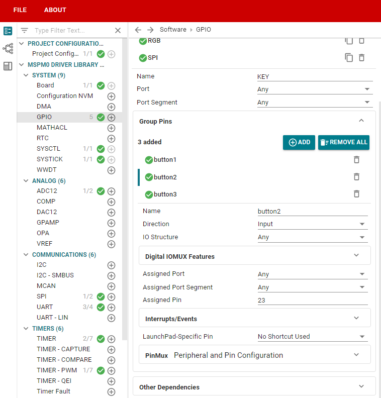
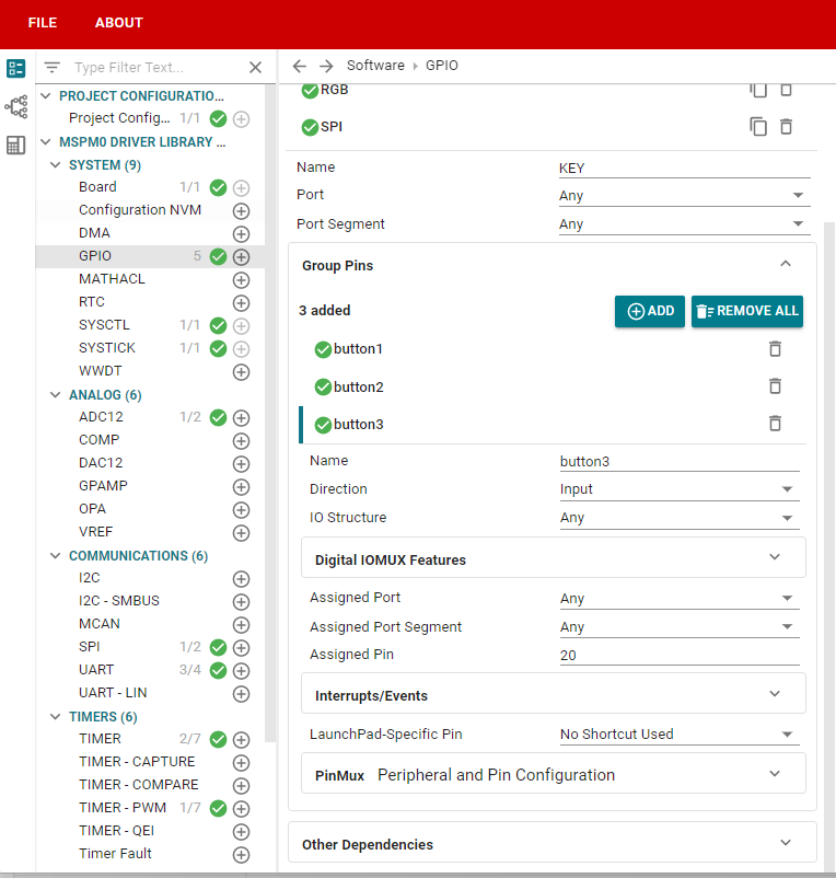
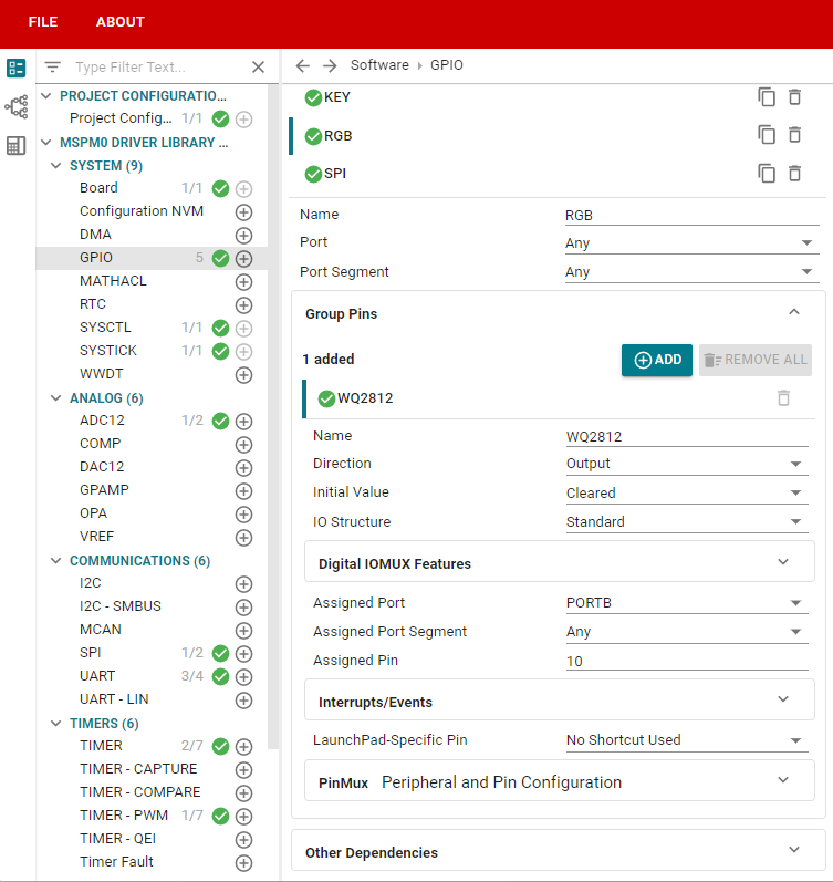
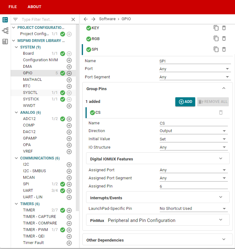
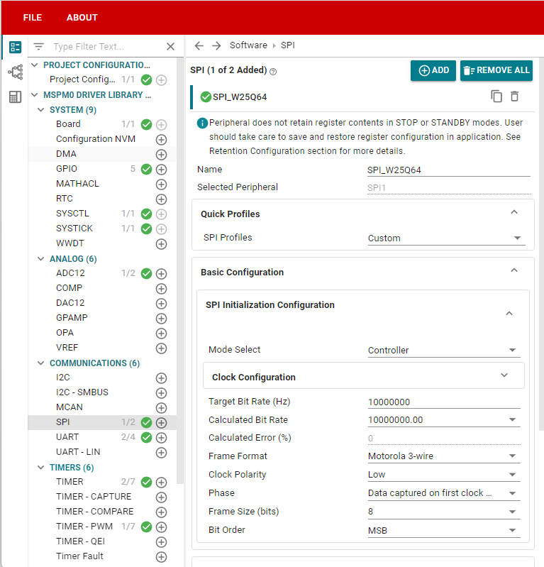
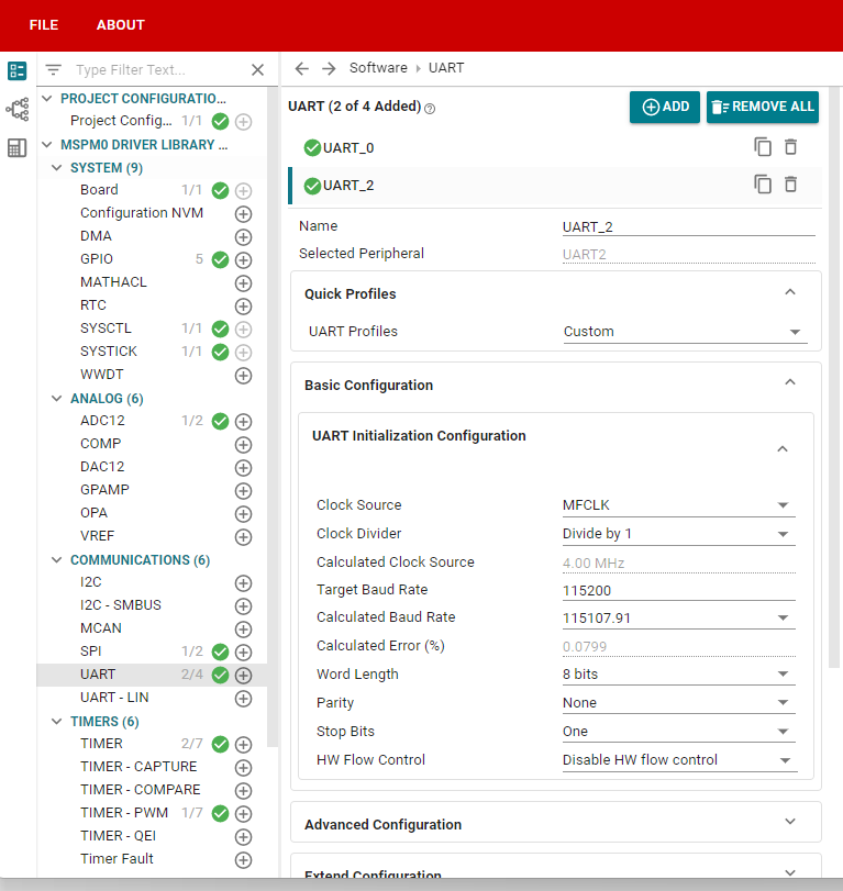
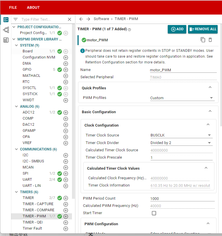
4. Main Functions
4.1 User Functions
Function: Send_k230
| Function Prototype | void Send_k230(uint8_t *data_str, uint16_t datasize) |
|---|---|
| Function Description | Control the state of RGB light on k230 |
| Input Parameter 1 | Data |
| Input Parameter 2 | Data length |
| Output Parameters | None |
Function: Deal_k230
| Function Prototype | void Deal_k230(uint8_t recv_msg) |
|---|---|
| Function Description | Retain k230 information |
| Input Parameters | Information from serial port |
| Output Parameters | None |
Function: BSP_Loop
| Function Prototype | void BSP_Loop(void) |
|---|---|
| Function Description | Use button, press once to send data to k230 |
| Input Parameters | None |
| Output Parameters | None |
Communication Protocol:
K230 part:
Receiving part: When receiving MCU data from serial port, parse it, then RGB light will give corresponding color feedback.
Sending part: k230 will send color data through serial port, format is "$" + color name + "#".
MCU part:
Sending part: When pressing expansion board button, will send color data to k230 through serial port.
Receiving part: Receive data sent by k230 through serial port, and process each bit of data.
Data frame judgment: If it's "$", set flag to 1, then initialize string array; then process next bit of data, if it's not "#", store content in data. Until "#" is recognized, set flag to 0, then process array data. When array content comparison matches specific content, RGB light on car expansion board will give corresponding color feedback.
5. Experimental Phenomenon
After downloading the program, we connect the wiring between k230 and expansion board. Then we control the RGB light of k230 through function buttons on the expansion board.
When we press key1 button, k230's RGB light will light up one color. Pressing key1 once will light up one color;
When we press key2 button, k230's RGB light will light up other three colors (different from the three colors when pressing key1), pressing key2 once will light up one color;
When we press key3 button, k230's RGB light will turn off.
xxxxxxxxxxFor program download, refer to 【3. Development Environment Setup and Usage: 3. Uniflash burning】
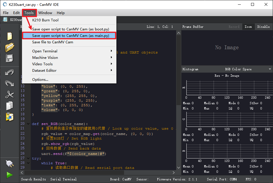
How to download k230 code:
Required tools: K230, SD card, CanMV IDE K230
We find the K230uart_car.py file in the project folder, then drag it to CanMV IDE K230, then select to save the opened script as main.py to CanMV. For detailed steps, please refer to the K230 Vision Module tutorial's 【Quick Start】 chapter.