Welcome to MSPM0 Smart Robot Car repository
19.K230 OCR character recognition
K230 OCR Character Recognition Action
K230 OCR Character Recognition Action1. Software-Hardware Requirements2. Basic Principles2.1 Hardware Schematic Diagram2.2 Physical Connection Diagram2.3 Control Principle3. Code Analysis4. Experimental Operation5. Experimental Phenomena
This tutorial is a comprehensive experiment combining multiple peripherals. It is recommended to understand individual peripherals before proceeding with this experiment.
1. Software-Hardware Requirements
KEIL5
MSPM0G3507 Robot Development Board
K230 module: External connection
Type-C Data Cable or DAP-Link
For program download or simulation to the development board
2. Basic Principles
2.1 Hardware Schematic Diagram
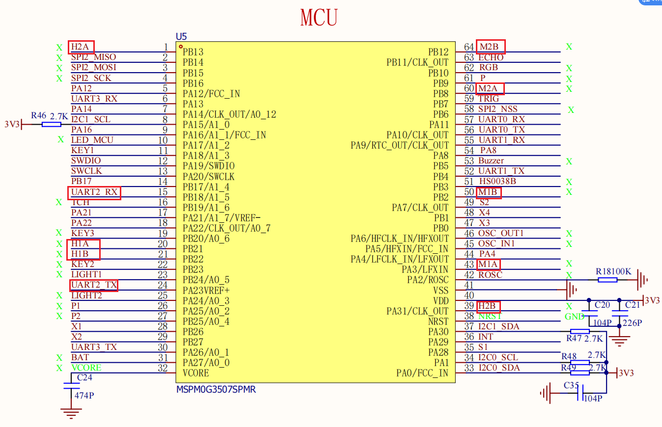
.png)
2.2 Physical Connection Diagram
.png)
Wiring Pins
Motor Wiring (Note: The wiring in the diagram below is for position reference only. Our factory provides dual-head PH2.0 6Pin all-black cables with anti-mistake design, so you don't need to worry about wiring issues)
| TT Encoder Motor | MSPM0G3507 |
|---|---|
| Motor Wire - | M1- |
| Motor Wire + | M1+ |
| Encoder Power | 3V3 |
| Encoder Output B Phase | H1B |
| Encoder Output A Phase | H1A |
| Encoder Ground | GND |
| TT Encoder Motor | MSPM0G3507 |
|---|---|
| Encoder Ground | GND |
| Encoder Output A Phase | H2A |
| Encoder Output B Phase | H2B |
| Encoder Power | 3V3 |
| Motor Wire + | M2+ |
| Motor Wire - | M2- |
K230 Wiring (Note: The wiring in the diagram below is for position reference only. Our factory provides K230 dual-head PH2.0 4Pin all-black cables with anti-mistake design, so you don't need to worry about wiring issues)
| K230 | MSPM0G3507 |
|---|---|
| RX | TX2 |
| TX | RX2 |
| GND | GND |
| 5V | 5V |
2.3 Control Principle
- Program Flowchart
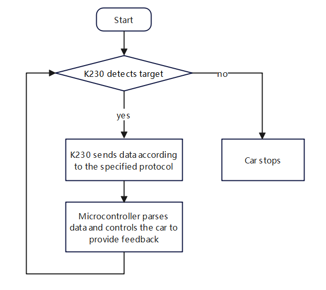
Control Principle:
PID Control
PID control is a commonly used closed-loop control algorithm that continuously adjusts the controller output to minimize the error between the system's actual output and expected output.
| PID Parameter | Function | Purpose |
|---|---|---|
| P (Proportional) | Determines the response speed of PID controller output | Accelerate system response speed |
| I (Integral) | Determines the response degree of PID controller to accumulated errors | Eliminate steady-state errors |
| D (Differential) | Determines the response degree of PID controller to error change rate | Improve system steady-state performance |
| Module | Function |
|---|---|
| K230 Vision Module | Recognizes the OCR characters you place, then sends data to microcontroller via serial port |
Communication Protocol:
When K230 recognizes OCR characters, it will send a data frame via serial port with the following format:
| Experiment Routine | Start Symbol | Length | Separator | Routine Number | Separator | x | Separator | y | Separator | w | Separator | h | End Symbol |
|---|---|---|---|---|---|---|---|---|---|---|---|---|---|
| Color Recognition | $ | XX | , | 13 | , | XXX | , | XXX | , | XXX | , | XXX | # |
Microcontroller part:
Receives data sent by K230 via serial port and processes each byte of data. Extracts valid data from the data frame content and stores it in an array. Then performs PID processing on the array data, and the microcontroller drives the motor movement using the processed data.
3. Code Analysis
Main Function Analysis
Function: Pto_Loop
| Function Prototype | void Pto_Loop(void) |
|---|---|
| Function Description | Main function for running the program |
| Input Parameters | None |
| Output Parameters | None |
Partial Function Analysis
- main.c
xColorMode color_mode = 2; //1:巡线、2:跟踪 1: Patrol, 2: Trackingint main(void){ bsp_init();//需要的外设初始化 Required peripheral initialization Control_RGB_ALL(OFF);//关闭RGB Turn off RGB delay_ms(100); OLED_ShowString(0,0,"pid_output:",8,1);//显示pid输出用于控制左右 Display PID output for left-right control OLED_ShowString(0,20,"pid_output1:",8,1);//显示pid输出用于控制前后 Display PID output for forward-backward control OLED_Refresh(); while (1) { Pto_Loop(); OLED_ShowSNum(75,0, pid_output, 3, 8, 1); OLED_ShowSNum(75,20,pid_output1,3,8,1); OLED_Refresh(); }}BSP_init: Hardware initialization
pto__Loop: Continuously processes received K230 messages.
- yb_protocol.c
xxxxxxxxxx/** * @Brief: 数据分析 Data analysis * @Note: * @Parm: 传入接受到的一个数据帧和长度 Pass in a received data frame and length * @Retval: */void Pto_Data_Parse(uint8_t *data_buf, uint8_t num){ uint8_t pto_head = data_buf[0]; uint8_t pto_tail = data_buf[num-1]; //校验头尾 Check head and tail if (!(pto_head == PTO_HEAD && pto_tail == PTO_TAIL)) { //DEBUG_PRINT("pto error:pto_head=0x%02x , pto_tail=0x%02x\n", pto_head, pto_tail); return; } uint8_t data_index = 1; uint8_t field_index[PTO_BUF_LEN_MAX] = {0}; int i = 0; int values[PTO_BUF_LEN_MAX] = {0}; char msgs[][PTO_BUF_LEN_MAX] = {0}; //分割字段 Split Field for (i = 1; i < num-1; i++) { if (data_buf[i] == ',') { data_buf[i] = 0; field_index[data_index] = i; data_index++; } } //解析长度与功能ID Parsing length and function ID for (i = 0; i < 2; i++) { values[i] = Pto_Char_To_Int((char*)data_buf+field_index[i]+1); } uint8_t pto_len = values[0]; uint8_t pto_id = values[1]; ParseCommonFields(pto_id,data_buf,pto_len,field_index,data_index,values,msgs);}Parses received data that conforms to the protocol, obtains the function ID and data information from the data, and executes the corresponding function handler. This project uses a metadata parsing method. The core idea is to separate the protocol format description (field positions, types, etc.) from parsing logic, defining protocol format through data structures (like struct arrays), and parsing functions automatically process data according to these descriptions.
Different types of data in the protocol can also be parsed. If you want to understand implementation details, you can study it yourself; no excessive explanation will be provided. This function has been adapted for all K230 communication protocols in our store, so it can be used normally without complete understanding.
- bsp_PID_motor.c
xxxxxxxxxx// PID单独计算一条通道 PID calculates one channel separatelyfloat PID_Calc_One_Motor(uint8_t motor_id, float now_speed){ if (motor_id >= MAX_MOTOR) return 0; return PID_Location_Calc(&pid_motor[motor_id], now_speed); }void Set_PID_Motor(float set_l ,float set_r,float turn_out){ l_pid_out = PID_Calc_One_Motor(0, set_l); r_pid_out = PID_Calc_One_Motor(1, set_r); PWM_Control_Car(l_pid_out+turn_out , r_pid_out-turn_out );}// 位置式PID计算方式//Position PID calculation methodfloat PID_Location_Calc(PID_t *pid, float actual_val){ /*计算目标值与实际值的误差*/ /*Calculate the error between the target value and the actual value*/ pid->err = pid->target_val - actual_val; /* 限定闭环死区 */ /*Limited closed-loop dead zone*/ if ((pid->err >= -40) && (pid->err <= 40)) { pid->err = 0; pid->integral = 0; } /* 积分分离,偏差较大时去掉积分作用 */ /*Integral separation, removing the integral effect when the deviation is large*/ if (pid->err > -1500 && pid->err < 1500) { pid->integral += pid->err; // error accumulation 误差累积 /* Limit the integration range to prevent integration saturation 限定积分范围,防止积分饱和 */ if (pid->integral > 4000) pid->integral = 4000; else if (pid->integral < -4000) pid->integral = -4000; } /*PID算法实现*/ /*PID algorithm implementation*/ pid->output_val = pid->Kp * pid->err + pid->Ki * pid->integral + pid->Kd * (pid->err - pid->err_last); /*误差传递*/ /*Error transmission*/ pid->err_last = pid->err; /*返回当前实际值*/ /*Returns the current actual value*/ return pid->output_val;}Set_PID_Motor: Sets target values for 2 motors and the turning loop output value.
PID_Calc_One_Motor: Calculates the position loop PID value for one channel and returns the calculated value.
PID_Location_Calc: Position loop PID calculation formula and complete position loop structure.
- bsp_K230_control.c
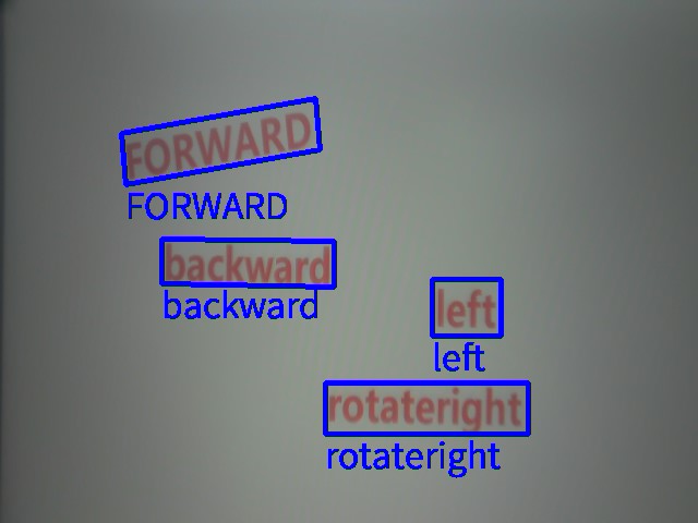
xxxxxxxxxxvoid OCRrec_Actions(const char* msg){ if(strcmp(msg,"FORWARD")==0 || strcmp(msg,"forward")==0) { Set_PID_Motor(70,70,0); delay_ms(1000); delay_ms(1000); Motor_Stop(1) ; } else if(strcmp(msg,"BACKWARD")==0 || strcmp(msg,"backward")==0) { Set_PID_Motor(-70,-70,0); delay_ms(1000); delay_ms(1000); Motor_Stop(1) ; } else if (strcmp(msg, "LEFT") == 0 || strcmp(msg, "left") == 0) { Set_PID_Motor(70,70,100); delay_ms(1000); delay_ms(1000); Motor_Stop(1) ; } else if (strcmp(msg, "RIGHT") == 0 || strcmp(msg, "right") == 0) { Set_PID_Motor(70,70,-100); delay_ms(1000); delay_ms(1000); Motor_Stop(1) ; } else if (strcmp(msg, "ROTATELEFT") == 0 || strcmp(msg, "rotateleft") == 0) { Set_PID_Motor(0,0,100); delay_ms(1000); delay_ms(1000); Motor_Stop(1) ; } else if (strcmp(msg, "ROTATERIGHT") == 0 || strcmp(msg, "rotateright") == 0) { Set_PID_Motor(0,0,-100); delay_ms(1000); delay_ms(1000); Motor_Stop(1) ; } else { Motor_Stop(1) ; }}OCRrec_Actions: When the recognized character content is "FORWARD", move forward for two seconds; when recognized as "BACKWARD", move backward for two seconds; "LEFT" for turning left for two seconds; "RIGHT" for turning right for two seconds; "ROTATELEFT" for rotating left for two seconds; "ROTATERIGHT" for rotating right for two seconds.
4. Experimental Operation
- Connect hardware according to the tutorial's wiring instructions.
- Open the project used by MSPM0G3507, then compile and burn the program, finally reset or power on again.
- Place OCR_Rec_Action.py in the root directory of K230's SD card and rename it to main.py, then reset or power on again. If you are not sure how to flash programs to K230, please first check the K230 Vision Module tutorial's [Quick Start] chapter.
- Place the car in an open area, then place OCR characters in front of the car, adjust the K230 module bracket to a suitable angle, and connect the power supply.
- When K230 initialization is successful, it will start recognizing OCR character content. Then press the car's reset button, wait for three seconds, and the car will move according to the recognized characters.
5. Experimental Phenomena
Turn on the power switch, wait for system initialization to complete. The screen will display the camera feed, then start recognizing characters and print the recognized character content on the screen. If the content matches the preset content in the OCRrec_Actions function, it will perform the corresponding actions.