Welcome to MSPM0 Smart Robot Car repository
8. Window Watchdog (WWDG)
Window Watchdog Mode
Window Watchdog ModeI. Learning ObjectivesII. Watchdog IntroductionIII. Experiment StepsIV. Code AnalysisV. Experiment Phenomenon
I. Learning Objectives
- Understand watchdog knowledge
- Learn to use the window watchdog mode on the MSPM0 development board
II. Watchdog Introduction
The main function of the Window Watchdog Timer (WWDT) is to trigger a reset operation when the device fails to operate normally due to unexpected software or system delays. The WWDT can preset a time window, and the application needs to restart the timer within this window to indicate that the program is executing normally. If the application does not restart the timer within the specified window, the WWDT sends a WWDT fault signal to the System Control Module (SYSCTL), which then generates a reset command. The MSPM0 microcontroller WWDT runs from the 32kHz low-frequency clock (LFCLK). The clock divider supports dividing the input clock from /1 (no division) to /8 (divide by 8) using the CLKDIV field in the WWDTCTL0 register. By running from LFCLK, the WWDT time base is independent of the main clock (MCLK) and CPU clock (CPUCLK) time bases, provided these clocks are not also configured to run from LFCLK. Although the time base can be considered independent and from a separate oscillator source, the LFCLK edges are synchronized. If the watchdog function is not needed in the application, the WWDT can also be configured as a basic system interval timer that can generate periodic maskable interrupts to the central processing unit (CPU).
I. Key Features of WWDT
- 25-bit counter with closed window and open window
- Counter driven by low-frequency clock (LFCLK, fixed 32kHz clock path) with programmable clock divider
- Eight selectable watchdog timer periods
- Counter can optionally auto-pause when operating in low-power mode
- Supports standard window watchdog mode or interval timer (non-watchdog) mode
II. WWDT Instances and Reset Types
The device may contain 1 or 2 WWDT instances, with different instances triggering different reset types:
- WWDT0: Generates boot reset (BOOTRST) on fault, resets peripherals and CPU state, and triggers boot configuration routine (BCR) execution.
- WWDT1: Generates system reset (SYSRST) on fault, only resets peripherals and CPU state, does not trigger BCR execution.
Therefore, WWDT1 is very suitable for recovering from execution stalls caused by software execution; while WWDT0 has a longer reset time but is more suitable for detecting serious problems (such as trim value corruption). For details, please refer to the data sheet
III. Window Watchdog Mode
In watchdog mode, the WWDT is configured to count to a specified WWDT period. The WWDT counter must be restarted (feed dog operation) within the configured "open window" of the WWDT period, otherwise the WWDT will assert a WWDT violation to the system control (SYSCTL) and generate a reset.
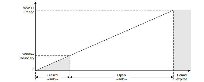
The window watchdog timer supports detecting "too late" and "too early" responses by using an optional "closed window". The WWDT period consists of a "closed window period" and an "open window period". The "closed window period" starts first, followed by the "open window period". The WWDT can only be restarted within the "open window period". If an attempt is made to restart the WWDT within the "closed window period", it will cause a violation. After the "closed window", if the WWDT is not restarted before the end of the "open window", the WWDT period will expire, which will also generate a violation.
If the "closed window" function is not needed, it can be disabled (set to 0%), which will give the functionality of a traditional watchdog timer, where the WWDT can be reset at any time before the WWDT period expires
The schematic diagram is as follows
III. Experiment Steps
This time we use the template routine from the 80MHz clock frequency configuration chapter.
We first open the sysconfig file and add the configuration as follows
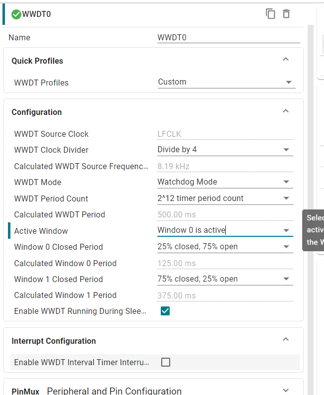
Parameter introduction
WWDT Source Clock: Clock source for the window watchdog peripheral, here is an independent internal low-speed clock of approximately 32.768Khz
WWDT Clock Divider: Clock division factor, 1-8 selectable
WWDT Mode: Different from the previous section, window watchdog mode is selected here
WWDT Period Count: Window watchdog period count value, maximum is 2^25, here configured as 500ms by matching with the division factor
Enable WWDT Running During Sleep...: Allow window watchdog to operate in low-power mode
Enable WWDT Interval Timer interrupt: Enable window watchdog interval timer interrupt
Activate Window: The window watchdog can configure two closed windows and then select them through this option. Here we set the effective closed window as window 0, window 1 setting is invalid (you can switch to mode 0 to try by yourself if the feed dog time is inappropriate)
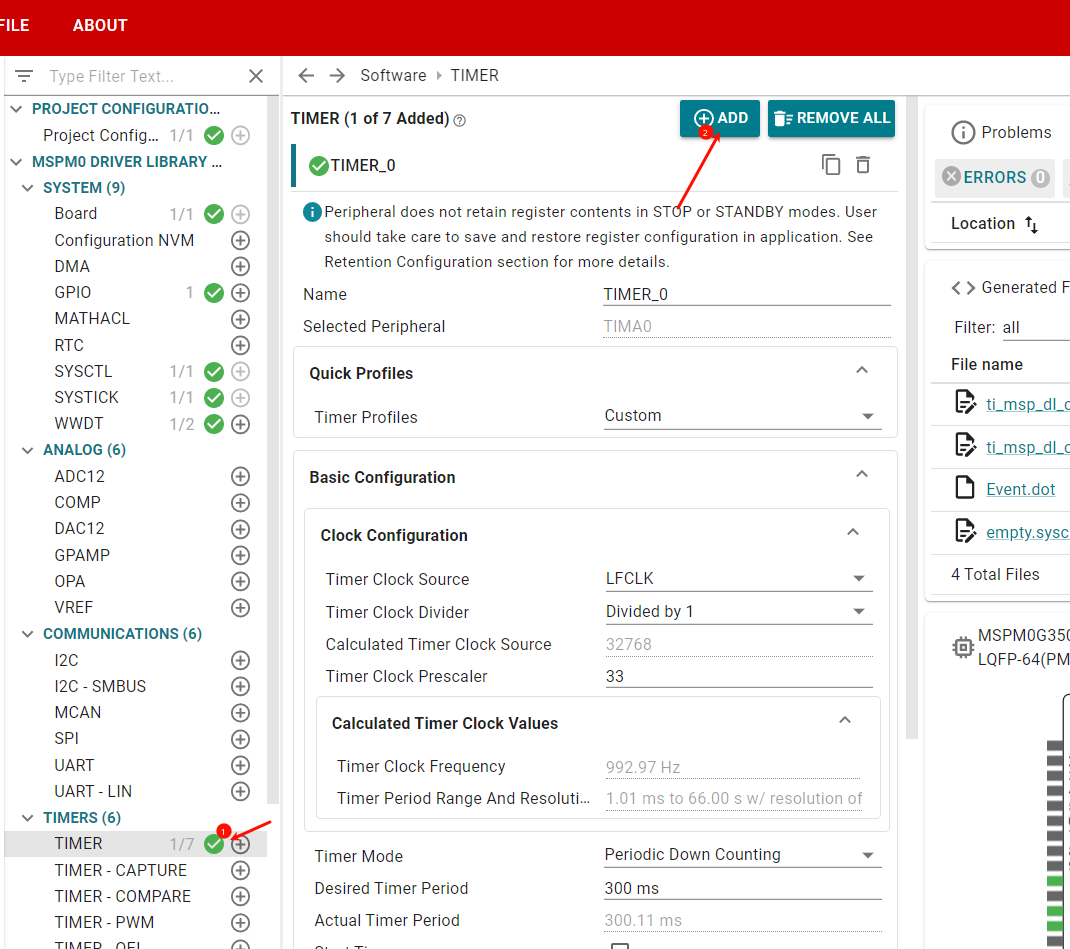
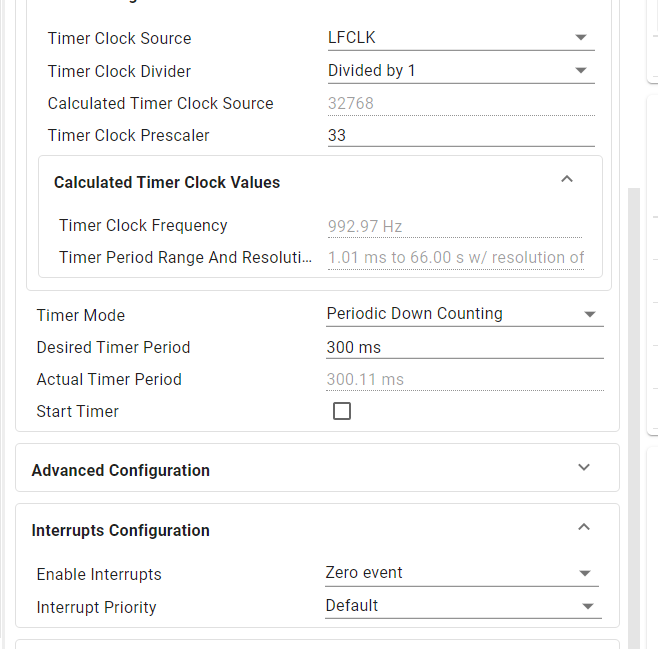
We add a timer to feed the dog
Then press CTRL+S to save and generate code
IV. Code Analysis
x
void TIMER_0_INST_IRQHandler(void){ switch (DL_TimerG_getPendingInterrupt(TIMER_0_INST)) { //定时器更新中断实现喂狗 //Timer update interrupt case DL_TIMER_IIDX_ZERO: /* Restart WWDT timer */ /*喂狗*/ DL_WWDT_restart(WWDT0_INST); /*喂狗完成翻转LED*/ /* Toggle LED to indicate WWDT reset */ DL_GPIO_togglePins(LED_PORT, LED_MCU_PIN ); break; default: break; }}V. Experiment Phenomenon
Every 500ms, the MCU status indicator LED state toggles once. You can switch the effective window of the window watchdog in sysconfig and observe the phenomenon after recompiling and flashing.