yahboom
HomeLearn
Solution
Blog
Online Store
About Us
EN/中文
MSPM0 Smart Robot Car📖
1.Quick Start Guide
  • 1. Assembly Videos
  • 2. Quick Start Videos
  • 3. Battery charging
  • 4. Notes
2.Introduction to the MSPM0 Car
  • 1.About MSPM0
  • 2.Development board interface description
3.Development environment setup and usage
  • 1.CCS Theia development
  • 2.MDK Arm development
  • 3.Uniflash burning
  • 4.External crystal oscillator configuration
  • 5.Project Migration
4.MSPM0 basic course
  • 1. LED light control (GPIO)
  • 2. Buzzer Control (GPIO)
  • 3. Button Control (EXTI)
  • 4. Serial Port (UART)
  • 5. Voltage Detection (ADC)
  • 6. Temperature Detection (ADC)
  • 7. Independent Watchdog (WWDG)
  • 8. Window Watchdog (WWDG)
  • 9. Timer (TIM)
  • 10. Breathing LED (PWM)
  • 11. I2C Communication (I2C)
  • 12. External Flash (SPI)
  • 13. Internal Flash (Flash)
  • 14. DMA
  • 15. FreeRTOS
5.Sensor basic course
  • 1.Servo control
  • 2.Ultrasonic servo PTZ basic use
  • 3.Motor PID control
  • 4.OLED display photosensitive value
  • 5.Infrared avoid sensor
  • 6.1 Infrared line tracking sensor-8 channel infrared tracking sensor module
  • 6.2 Infrared line tracking sensor-4 channel infrared tracking sensor module
  • 7.Infrared remote control
  • 8.Ultrasonic ranging
  • 9.RGB light drive
  • 10.MPU6050 raw data acquisition
  • 11.MPU6050 data fusion
  • 12.K210 vision recognition module
  • 13.K230 vision recognition module
6.Smart car course
  • 1.1 Car line tracking-8 channel infrared tracking sensor module
  • 1.2 Car line tracking-4 channel infrared tracking sensor module
  • 2.1 Drawing a circle-8 channel infrared tracking sensor module
  • 2.2 Drawing a circle-4 channel infrared tracking sensor module
  • 3.Ultrasonic following
  • 4.Ultrasonic avoid
  • 5.Ultrasonic avoid(Servo PTZ)
  • 6.Infrared sensor avoid
  • 7.Light following
  • 8.Gyroscope calibration straight-line walk
  • 9.Infrared remote control
  • 10.Autonomous driving car
7.Vision application course
  • 1.K210 autonomous driving
  • 2.K210 color tracking
  • 3.K210 handwritten digit action
  • 4.K210 color response
  • 5.K210 road sign indication action
  • 6.K210 following machine code
  • 7.K210 QR code command
  • 8.K230 vision line tracking
  • 9.K230 color tracking
  • 10.K230 machine code tracking
  • 11.K230 QR code command
  • 12.K230 autonomous avoid
  • 13.K230 license plate tracking
  • 14.K230 face tracking
  • 15.K230 gaze direction tracking
  • 16.K230 palm tracking
  • 17.K230 target tracking
  • 18.K230 human body tracking
  • 19.K230 OCR character recognition
8.Extended application course (Sold separately)
  • 1.Voice interaction module communication
  • 2.Voice interaction control
  • 3.K230 road sign indication action(Voice)
  • 4.K230 color response(Voice)
  • 5.K230 gesture control(Voice)
  • 6.K230 rock-paper-scissors(Voice)
  • 7.8-channel grayscale color line tracking
  • 8.Bluetooth remote control
  • 9.K210 Scenario-based autonomous driving
  • 10.K230 Scenario-based autonomous driving
Download
  • Code
  • SCH
  • 3D Model File
  • MSPM0 Data Sheet
  • Voice firmware
  • Hardware interface manual
Download ZIP

Welcome to MSPM0 Smart Robot Car repository

3.Ultrasonic following

Ultrasonic Following

Ultrasonic Following1. Ultrasonic Module Introduction2. Hardware Connection3. Partial Code Analysis4. Main Functions5. Experimental Phenomenon

1. Ultrasonic Module Introduction

is a module that uses ultrasound for non-contact physical measurement. It can accurately measure physical quantities such as distance, speed, and flow rate by emitting and receiving ultrasonic signals, and converts measurement results into digital signal output. This article will explain the working principle and function of ultrasonic modules.

Main types of ultrasonic modules on the market:

  • HC-SR04 Ultrasonic Module
  • US-100 Ultrasonic Module
  • US-015 Ultrasonic Module
  • HY-SRF05 Ultrasonic Ranging Module
  • HC-SR04 Ultrasonic Ranging Module

This experiment's ultrasonic module information: HC-SR04

Ranging Principle: Input a high-level signal of more than 10 microseconds to the trigger end of the ultrasonic module to emit ultrasonic waves. After emitting ultrasonic waves and before receiving the returned ultrasonic waves, the receiving end is at high level. Therefore, the program can calculate the distance of the measured object from the high-level pulse duration of the "response" pin. Test Distance = (High Level Time * Sound Speed (340M/S)) / 2;
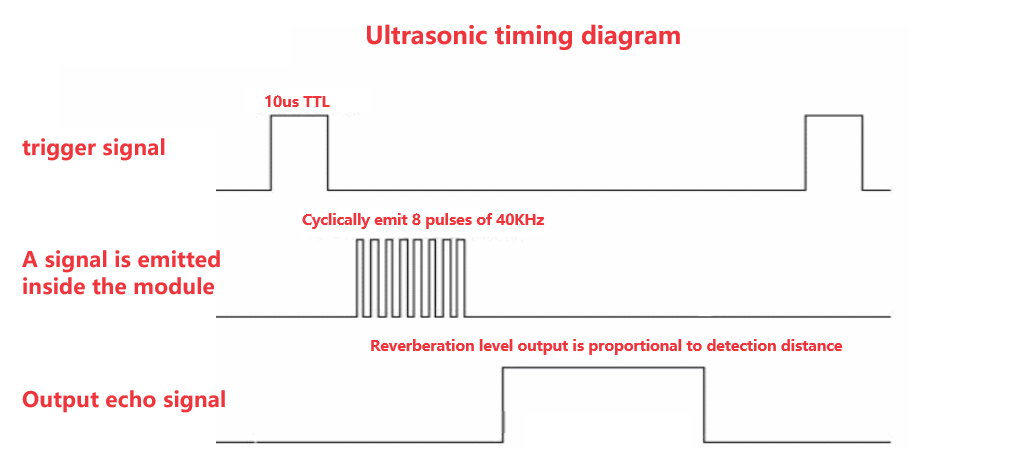
image-20230926100744845

Note: The above timing diagram shows that only a 10us or more pulse trigger signal needs to be provided. The module internally will emit 8 40kHz cycle levels and detect echoes. Once an echo signal is detected, it outputs a response signal. The pulse width of the response signal is proportional to the measured distance. Therefore, the distance can be calculated from the time interval between transmitting the signal and receiving the response signal.

2. Hardware Connection

Ultrasonic ModuleMSPM0G3507
VCCVCC
TrigTrig
EchoEcho
GNDGND

未命名的设计 (41)

upscalemedia-transformed (28)


Control Flowchart

Distance greater than upper limit
Distance between upper and lower limits
Yes
No
Distance less than lower limit
Start
Ultrasonic Distance
Accelerate Forward
Distance less than stop value
Stop
Decelerate Forward
Reverse

3. Partial Code Analysis

bsp_ultrasonic.c

xxxxxxxxxx
// 获取测量距离 / Get measurement distance
float Hcsr04GetLength(void)
{
    volatile float sum = 0;
    volatile uint32_t pulse_time_us = 0;
    
    for(int i = 0; i < AVG_COUNT; i++) // 测5次取平均 / Measure 5 times and take average
    {
        // 发送触发脉冲 / Send trigger pulse
        SR04_TRIG(0);
        delay_us(2);
        SR04_TRIG(1);
        delay_us(15);  // 10-20us触发脉冲 / 10-20us trigger pulse
        SR04_TRIG(0);
        
​
        while(SR04_ECHO() == 0);
       
​
        // 记录起始时间(100us精度) / Record start time (100us accuracy)
        Open_Timer();
        uint32_t start_count = usHcCount;
        
        // 等待下降沿 / Wait for falling edge
        while(SR04_ECHO() > 0 );
        Close_Timer();
        // 计算脉冲时间(us) / Calculate pulse time (us)
        uint32_t end_count = usHcCount;
        pulse_time_us = (end_count - start_count) * 100; // 转换为us / Convert to us
        
        // 计算距离(标准公式:cm = us / 58) / Calculate distance (standard formula: cm = us / 58)
        sum += (pulse_time_us / 58.0f);
                
        delay_ms(5);
    }
    
    distance = sum / AVG_COUNT; // 计算平均值 / Calculate average
    return distance;
}
​
void ultrasonic_track()
{
        if(int_value <20)
        {
​
            if(int_value <=15)
                {
​
                 if(int_value <=10)
                    {
                        wheel_State(MOTION_BACK,100);
                    }
                    else if(int_value<=12)
                    {
                        Motion_Set_Speed(0,0);
                    }
                    else
                        Motion_Set_Speed(50,50);
                }
            else
                        Motion_Set_Speed(150,150);
            
        }
        else
            Motion_Set_Speed(200,200);
​
​
}

4. Main Functions

Hcsr04GetLength

Function Prototypefloat Hcsr04GetLength(void)
Function DescriptionMeasures distance through HC-SR04 ultrasonic sensor, takes average of AVG_COUNT consecutive measurements. Sends 10-20us trigger pulse, detects echo pulse width and converts to distance (unit: cm), formula: distance = pulse time (us) / 58
Input ParametersNone
Return Valuefloat type, average measured distance (cm)

ultrasonic_track

Function Prototypevoid ultrasonic_track()
Function DescriptionControls car movement based on ultrasonic measured distance (int_value): when distance is less than 20cm, decelerates, stops, or reverses according to different ranges; when distance is greater than or equal to 20cm, moves forward at speed 200
Input ParametersNone
Return ValueNone

5. Experimental Phenomenon

After connecting the car properly, connecting the OLED module, and burning the program to MSPM0, place your hand or an obstacle in front of the ultrasonic sensor, the car will maintain a certain distance from the obstacle. When the distance increases, the car moves forward; when the distance decreases, the car moves backward.


Drawing a circle-4 channel infrared tracking sensor module
Ultrasonic avoid

COMPANY

  • About us
  • Team Style
  • Blog

LEARNING & EXPLORATION

  • Tutorials
  • Edge AI hardware
  • Educational robots
  • Embedded intelligent hardware

WHERE TO BUY

  • Yahboom Online Store
  • Amazon
  • Alibaba
  • AliExpress
  • Mercado

TECHNOLOGY SUPPORT

  • Email: support@yahboom.com

BE A DISTRIBUTOR

  • Email: sales@yahboom.com
QR Code

Copyright © 2017-2026 Yahboom. All Rights Reserved.

EN/中文