yahboom
HomeLearn
Solution
Blog
Online Store
About Us
EN/中文
MSPM0 Smart Robot Car📖
1.Quick Start Guide
  • 1. Assembly Videos
  • 2. Quick Start Videos
  • 3. Battery charging
  • 4. Notes
2.Introduction to the MSPM0 Car
  • 1.About MSPM0
  • 2.Development board interface description
3.Development environment setup and usage
  • 1.CCS Theia development
  • 2.MDK Arm development
  • 3.Uniflash burning
  • 4.External crystal oscillator configuration
  • 5.Project Migration
4.MSPM0 basic course
  • 1. LED light control (GPIO)
  • 2. Buzzer Control (GPIO)
  • 3. Button Control (EXTI)
  • 4. Serial Port (UART)
  • 5. Voltage Detection (ADC)
  • 6. Temperature Detection (ADC)
  • 7. Independent Watchdog (WWDG)
  • 8. Window Watchdog (WWDG)
  • 9. Timer (TIM)
  • 10. Breathing LED (PWM)
  • 11. I2C Communication (I2C)
  • 12. External Flash (SPI)
  • 13. Internal Flash (Flash)
  • 14. DMA
  • 15. FreeRTOS
5.Sensor basic course
  • 1.Servo control
  • 2.Ultrasonic servo PTZ basic use
  • 3.Motor PID control
  • 4.OLED display photosensitive value
  • 5.Infrared avoid sensor
  • 6.1 Infrared line tracking sensor-8 channel infrared tracking sensor module
  • 6.2 Infrared line tracking sensor-4 channel infrared tracking sensor module
  • 7.Infrared remote control
  • 8.Ultrasonic ranging
  • 9.RGB light drive
  • 10.MPU6050 raw data acquisition
  • 11.MPU6050 data fusion
  • 12.K210 vision recognition module
  • 13.K230 vision recognition module
6.Smart car course
  • 1.1 Car line tracking-8 channel infrared tracking sensor module
  • 1.2 Car line tracking-4 channel infrared tracking sensor module
  • 2.1 Drawing a circle-8 channel infrared tracking sensor module
  • 2.2 Drawing a circle-4 channel infrared tracking sensor module
  • 3.Ultrasonic following
  • 4.Ultrasonic avoid
  • 5.Ultrasonic avoid(Servo PTZ)
  • 6.Infrared sensor avoid
  • 7.Light following
  • 8.Gyroscope calibration straight-line walk
  • 9.Infrared remote control
  • 10.Autonomous driving car
7.Vision application course
  • 1.K210 autonomous driving
  • 2.K210 color tracking
  • 3.K210 handwritten digit action
  • 4.K210 color response
  • 5.K210 road sign indication action
  • 6.K210 following machine code
  • 7.K210 QR code command
  • 8.K230 vision line tracking
  • 9.K230 color tracking
  • 10.K230 machine code tracking
  • 11.K230 QR code command
  • 12.K230 autonomous avoid
  • 13.K230 license plate tracking
  • 14.K230 face tracking
  • 15.K230 gaze direction tracking
  • 16.K230 palm tracking
  • 17.K230 target tracking
  • 18.K230 human body tracking
  • 19.K230 OCR character recognition
8.Extended application course (Sold separately)
  • 1.Voice interaction module communication
  • 2.Voice interaction control
  • 3.K230 road sign indication action(Voice)
  • 4.K230 color response(Voice)
  • 5.K230 gesture control(Voice)
  • 6.K230 rock-paper-scissors(Voice)
  • 7.8-channel grayscale color line tracking
  • 8.Bluetooth remote control
  • 9.K210 Scenario-based autonomous driving
  • 10.K230 Scenario-based autonomous driving
Download
  • Code
  • SCH
  • 3D Model File
  • MSPM0 Data Sheet
  • Voice firmware
  • Hardware interface manual
Download ZIP

Welcome to MSPM0 Smart Robot Car repository

7.8-channel grayscale color line tracking

8-channel Grayscale Color Line Tracking

8-channel Grayscale Color Line TrackingHardware WiringPartial Code AnalysisMain FunctionsExperimental Phenomena

Our store offers four types of 8-channel Grayscale Tracking Modules, distinguished by light color: Red, Green, Blue, White. Different colored grayscale modules are suitable for different line inspection scenarios. The provided source code is compatible with all sensors.

Sensor ClassificationRedGreenBlueWhite
White BackgroundGreen, Cyan, Blue, BlackRed, Blue, Purple, BlackYellow, Red, Green, BlackBlack
Black BackgroundRed, Orange, Yellow, WhiteGreen, Yellow, Cyan, WhiteBlue, Purple, Cyan, WhiteWhite

Hardware Wiring

8-channel Grayscale Tracking ModuleMSPM0G3507
5V5V
GNDGND
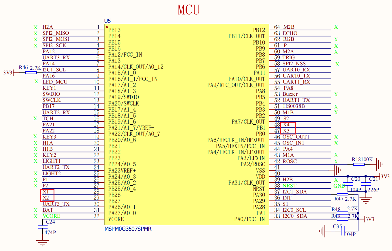
AD0X1
AD1X2
AD2X3
OUTX4

Start the trolley (19)

image-20251030204804857

Partial Code Analysis

Control Principle

Line tracking control logic
The deviation is calculated based on x1-x8 to obtain err
Obtain data from x1-x8 sensors
Steering amount is calculated using positional PID control.
The movement of the trolley is controlled based on the PID output.

Modify the active level by changing ACTIVE_VALUE to 0/1.

bsp_ir_eight.c

xxxxxxxxxx
/**
 * @brief Read the status of eight infrared sensors
 * @param ir_results An array of length 8 is used to store the state (0/1) of each path.
 */
void ReadEightIR(uint8_t ir_results[8]) {
​
    for (int channel = 0; channel < 8; channel++) {
        // Calculate the C, B, and A values ••corresponding to the current channel (C is the most significant bit, and A is the least significant bit).
        uint8_t c = (channel >> 2) & 0x01;
        uint8_t b = (channel >> 1) & 0x01;
        uint8_t a = channel & 0x01;       
        SET_CHANNEL(c, b, a); // Set channel selection pin  
        delay_ms(1);
        // Read the infrared status of the current channel and store it in the result array.
        ir_results[channel] = READ_IR_OUT() ? 1 : 0;
                
    }
}

bsp_ir_eight.h

xxxxxxxxxx
#define EIGHT_IR_PORT        Eight_IR_PORT   // port
#define EIGHT_IR_AD0_PIN     Eight_IR_AD0_X1_PIN    // Channel selection: A (least significant bit)
#define EIGHT_IR_AD1_PIN     Eight_IR_AD1_X2_PIN    // Channel selection: B
#define EIGHT_IR_AD2_PIN     Eight_IR_AD2_X3_PIN    // Channel selection: C (most significant bit)
#define EIGHT_IR_OUT_PIN     Eight_IR_OUT_X4_PIN    // Infrared detection output pin
​
​
// Set the level (0 or 1) of the channel selection pins C, B, and A.
#define SET_CHANNEL(c_val, b_val, a_val) \
    do { \
        GPIO_setPins(EIGHT_IR_PORT, EIGHT_IR_AD2_PIN, c_val); \
        GPIO_setPins(EIGHT_IR_PORT, EIGHT_IR_AD1_PIN, b_val); \
        GPIO_setPins(EIGHT_IR_PORT, EIGHT_IR_AD0_PIN, a_val); \
    } while(0)
​

Main Functions

ReadEightIR

Function Prototypevoid ReadEightIR(uint8_t ir_results[8])
Function DescriptionReads the status of eight infrared sensors and stores the status (0 or 1) of each channel into a specified array. Channels are selected by calculating the corresponding C, B, and A values. The status is read and stored after a 1ms delay.
Input Parametersir_results: An array of type uint8_t with a length of 8, used to store the status of eight infrared sensors (0 indicates no detection, 1 indicates detection).
Return ValueNone

Experimental Phenomena

After connecting the car to the OLED module and programming the MSPM0, place the car on a map with a white background and black lines. The car will automatically start tracking, and the sensor data will be displayed on the OLED.
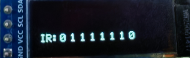
image-20251028191614823

K230 rock-paper-scissors(Voice)
Bluetooth remote control

COMPANY

  • About us
  • Team Style
  • Blog

LEARNING & EXPLORATION

  • Tutorials
  • Edge AI hardware
  • Educational robots
  • Embedded intelligent hardware

WHERE TO BUY

  • Yahboom Online Store
  • Amazon
  • Alibaba
  • AliExpress
  • Mercado

TECHNOLOGY SUPPORT

  • Email: support@yahboom.com

BE A DISTRIBUTOR

  • Email: sales@yahboom.com
QR Code
QR Code

Copyright © 2017-2026 Yahboom. All Rights Reserved.

EN/中文