Welcome to MSPM0 Smart Robot Car repository
7.Infrared remote control
Infrared Remote Control
Infrared Remote Control1. Software and Hardware2. Basic Principles2.1 Hardware Schematic2.2 Physical Connection Diagram2.3 Control Principle3. Project Configuration3.1 Description3.2 Pin Configuration4. Main Functions4.1 User Functions5. Experimental Phenomenon
This tutorial demonstrates: printing the corresponding key values of the infrared remote control through serial port 0
1. Software and Hardware
KEIL
MSPM0G3507 Development Board
Infrared Remote Control
Type-C data cable or DAP-Link
For programming download or simulation to the development board
2. Basic Principles
2.1 Hardware Schematic
.png)
2.2 Physical Connection Diagram
.png)
2.3 Control Principle
Receive infrared data through interrupt triggering, and determine whether the data is 0 or 1 based on the high-level duration of the infrared receiver's output pin, thereby achieving data reading of infrared remote control key values.
NEC Protocol
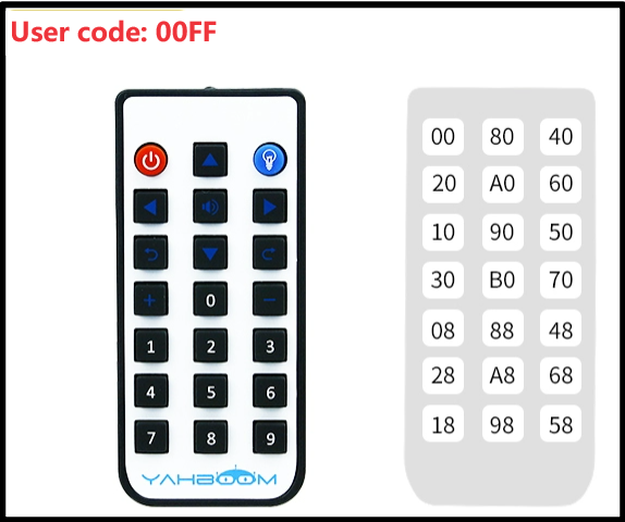
The remote control included with the development board uses the NEC protocol with a carrier frequency of 38KHz.
| Format | Function |
|---|---|
| Guide Code | Marks the beginning of instruction |
| Address Code (User Code) | Identifies the device address of the remote control |
| Address Inverse Code | Enhances data transmission reliability |
| Data Code | Specific remote control instruction |
| Data Inverse Code | Enhances data transmission reliability |

- Infrared Remote Control
0: Composed of 560us 38KHz carrier + 560us no-carrier interval
1: Composed of 560us 38KHz carrier + 1680us no-carrier interval
- Infrared Receiver
0: 560us low level + 560us high level
1: 560us low level + 1680us high level
When the infrared receiver receives infrared carrier signal, the DATA output pin of HS0038B outputs low level
When the infrared receiver does not receive infrared carrier signal, the DATA output pin of HS0038B outputs high level
| Infrared Receiver (Development Board Integrated) | Corresponding Pin |
|---|---|
| HS0038B | PB3 |
3. Project Configuration
3.1 Description
You can refer to the basic tutorial to complete the development environment setup.
3.2 Pin Configuration
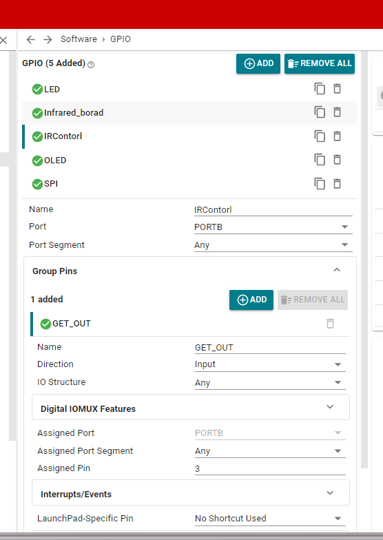
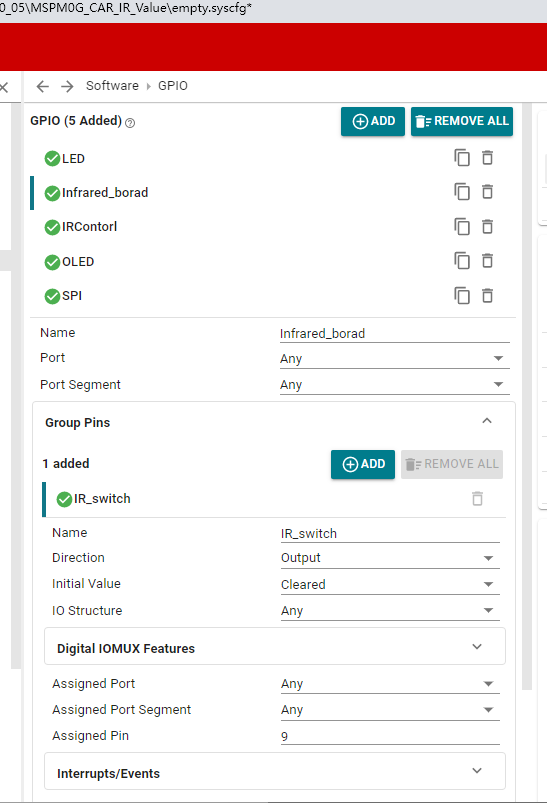
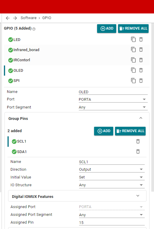
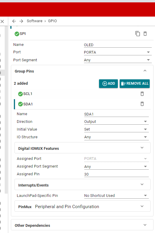
4. Main Functions
Mainly introduces the functional code written by users. For detailed code, you can open the project files we provide and view the source code in the Bsp folder.
4.1 User Functions
Function: receiving_infrared_data
| Function Prototype | uint8_t receiving_infrared_data() |
|---|---|
| Function Description | Receive infrared data |
| Input Parameters | None |
| Output Parameters | Infrared data |
Function: guide_and_repeat_code_judgment
| Function Prototype | uint8_t guide_and_repeat_code_judgment(void) |
|---|---|
| Function Description | Infrared data correctness judgment |
| Input Parameters | None |
| Output Parameters | 0 and 1 used to judge whether address code and command code are correct |
5. Experimental Phenomenon
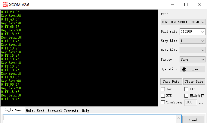
After successfully downloading the program, press the RESET button on the development board and observe the phenomenon on the serial port debugging assistant!
For program download, refer to 【3. Development Environment Setup and Usage: 3. Uniflash burning】
Phenomenon:
Press different key values on the infrared remote control, and the serial port will print different data corresponding to the key values.