Welcome to MSPM0 Smart Robot Car repository
6.2 Infrared line tracking sensor-4 channel infrared tracking sensor module
4-Channel Line Tracking Module
2.1 Module Introduction
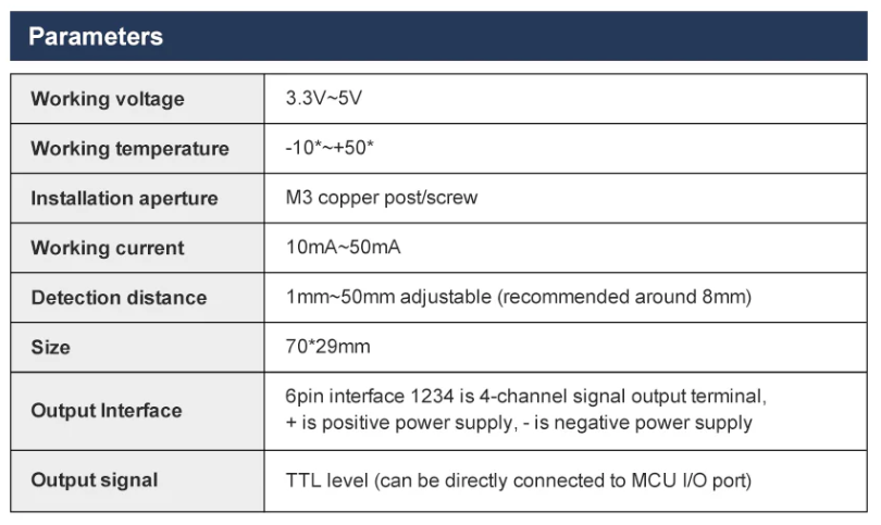
Basic Parameters
Testing Module
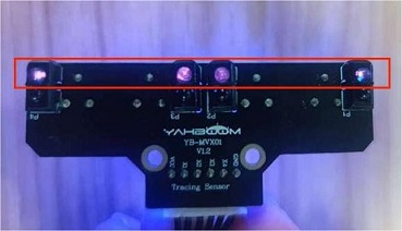
Connect the module's VCC and GND to the main board, other pins of the module do not need to be connected. Turn on the phone camera and aim it at the four-channel infrared sensor, you can see the four sensors emitting faint purple light.
Hold the module away from the desktop, as shown in the figure you can see 4 LED lights are on. Place your finger under one of the sensors, as shown in the figure you can see the corresponding LED light turn off. If this phenomenon occurs, it means the four-channel line tracking module can work normally.
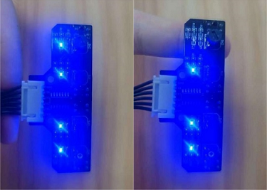
Note: If one of the LED lights does not change, just adjust the corresponding sensor knob to achieve this phenomenon
Actual Usage
Environment requirements: In indoor places with weak infrared light, the black track on the white surface must be greater than 16mm
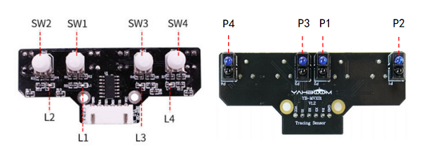
Four-channel line tracking module (front) Four-channel line tracking module (back)
Debugging (only connect VCC and GND pins of the module):
- Adjust potentiometer [SW1] so that when photoelectric sensor [P1] faces the white surface, LED light [L1] is off, and when facing the black line, LED light [L1] is on
- Adjust potentiometer [SW2] so that when photoelectric sensor [P2] faces the white surface, LED light [L2] is off, and when facing the black line, LED light [L2] is on
- Adjust potentiometer [SW3] so that when photoelectric sensor [P3] faces the white surface, LED light [L3] is off, and when facing the black line, LED light [L3] is on
- Adjust potentiometer [SW4] so that when photoelectric sensor [P4] faces the white surface, LED light [L4] is off, and when facing the black line, LED light [L4] is on
Note: During debugging, try to maintain the same height from the surface. When adjusting the potentiometer, the rotation range should not be too large, with a rotation range of less than 30 degrees. Slowly slide the module horizontally across the black line, you can see the LED lights turn on and off in sequence. At this time, it means the module has been debugged. If errors occur during subsequent use, simply readjust the potentiometer.
2.2 Hardware Wiring
| Four-Channel Line Tracking Module | MSPM0G3507 |
|---|---|
| 5V | 5V |
| GND | GND |
| X1 | X1 |
| X2 | X2 |
| X3 | X3 |
| X4 | X4 |
.png)
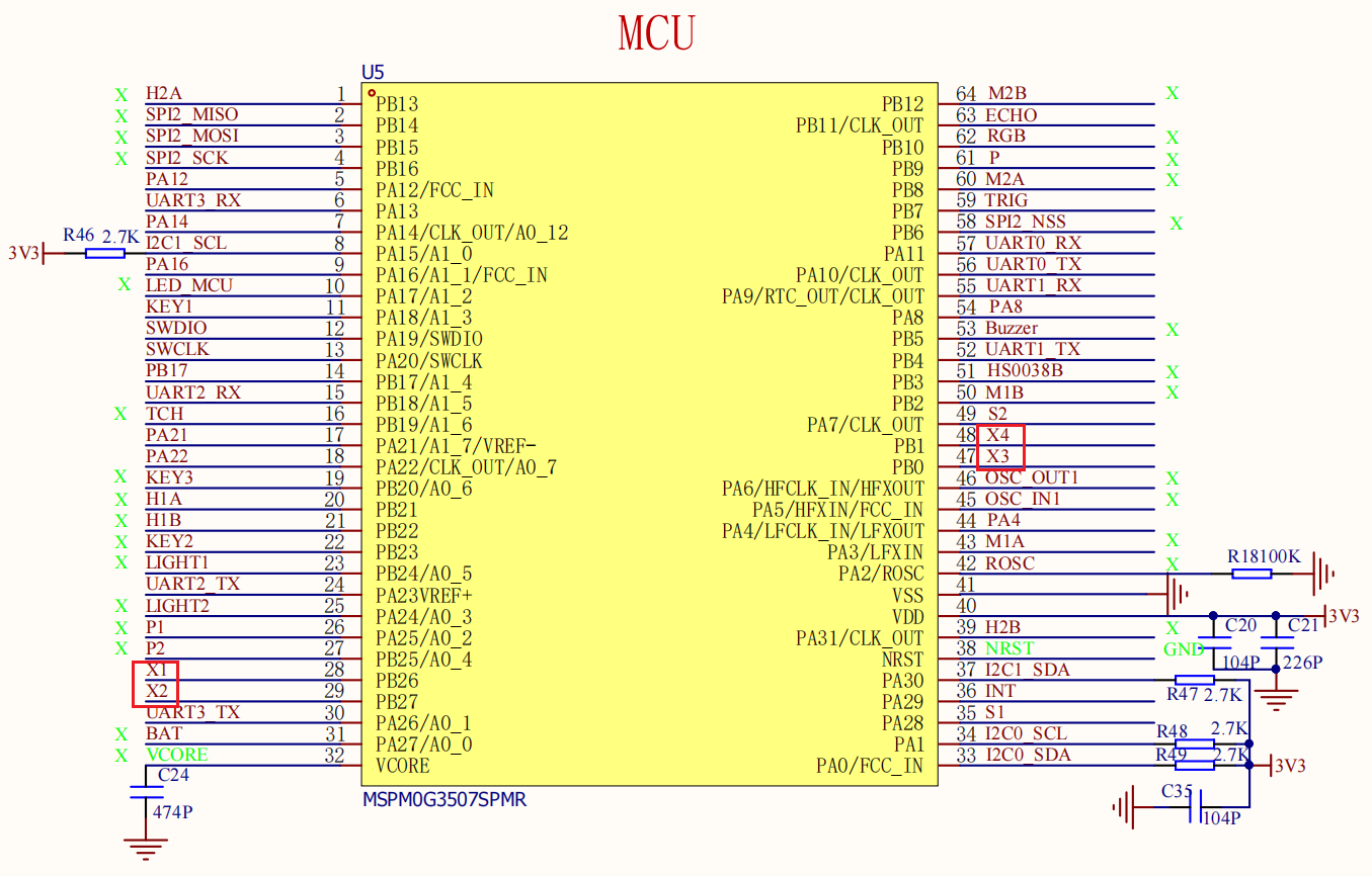
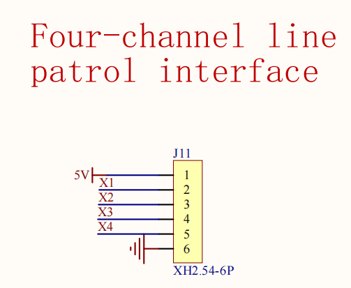
2.3 Environment Setup
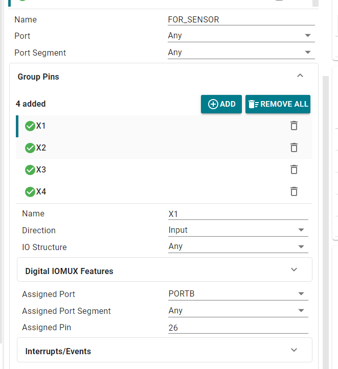
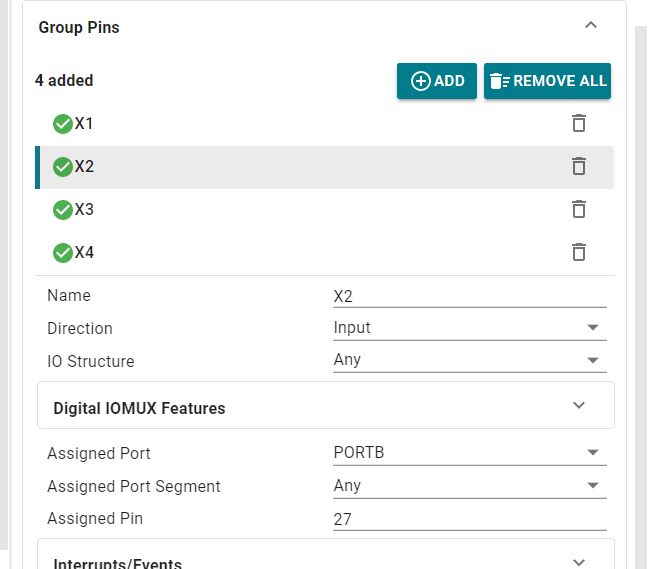
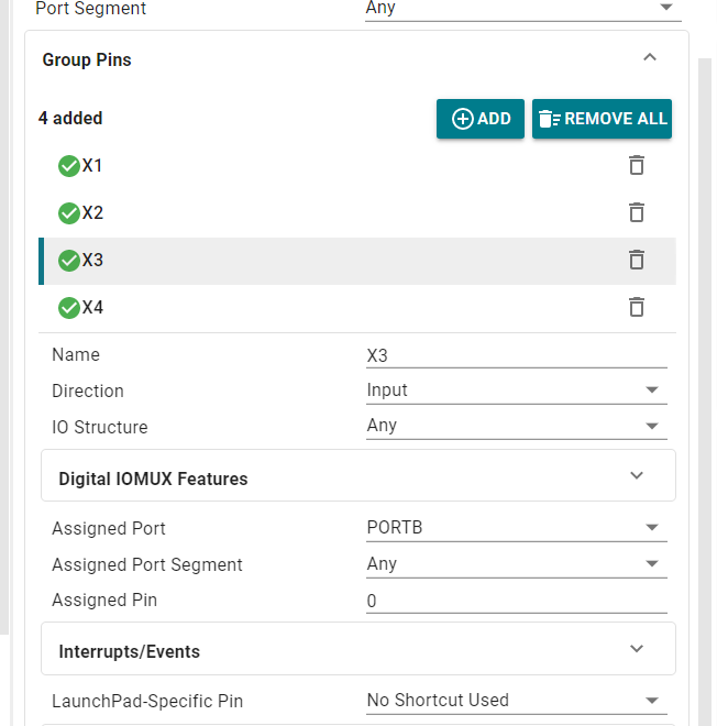
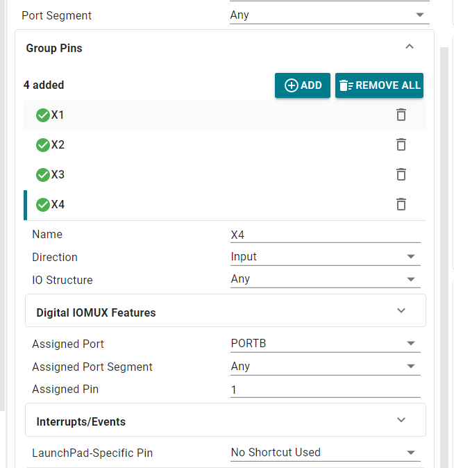
We open the sysconfig tool and add the following configuration. Here you can adjust your pin configuration according to the actual wiring. Other configurations are omitted here. For details, you can check the sysconfig file provided in the source code.
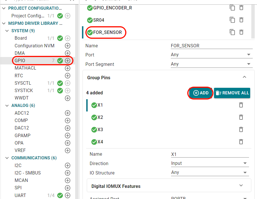
2.4 Main Functions
Four_GetLineWalking
| Function Prototype | void Four_GetLineWalking(int *LineL1, int *LineL2, int *LineR1, int *LineR2) |
|---|---|
| Function Description | Get the pin level status of four line tracking sensors (LineL1, LineL2, LineR1, LineR2) and return through pointers |
| Input Parameters | LineL1: pointer to variable storing the status of the first left sensor; LineL2: pointer to variable storing the status of the second left sensor; LineR1: pointer to variable storing the status of the first right sensor; LineR2: pointer to variable storing the status of the second right sensor |
| Return Value | None |
2.5 Experimental Phenomenon
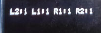
Connect the car wires, connect the OLED module, after burning the program to MSPM0, place the car on a map with white background and black lines, sensor data is displayed on the OLED
Where L2, L1, R1, R2 represent the four sensor data from left to right