Welcome to MSPM0 Smart Robot Car repository
5.K210 road sign indication action
K210 Road Sign Indication Action
K210 Road Sign Indication Action1. Hardware Connection2. Code Analysis3. Main Functions4. K210 Program Burning5. Experimental Phenomena
1. Hardware Connection
| K210 Vision Module | MSPM0G3507 |
|---|---|
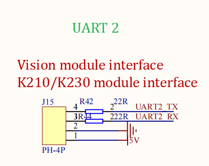
| 5V | 5V |
| GND | GND |
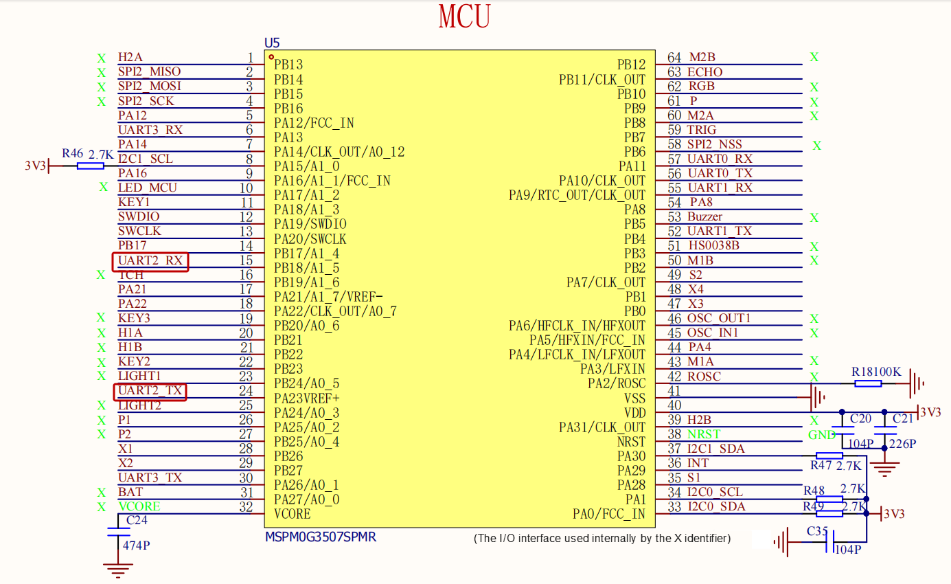
| TX | RX2 |
| RX | TX2 |
Physical Connection Diagram

Schematic Diagram
2. Code Analysis
Control Principle
K210 Protocol
| Header 1 | Header 2 | Length | Function Code | Car Type | X-axis Speed | X-axis Speed | Y-axis Speed | Y-axis Speed | Z-axis Speed | Z-axis Speed | checksum |
|---|---|---|---|---|---|---|---|---|---|---|---|
| 0xFF | 0xFC | 0x0A | 0x12 | XX | Low Byte | High Byte | Low Byte | High Byte | Low Byte | High Byte | XX |
Control Flow Chart
revaction.c
xxxxxxxxxx//数据分析 / data analysisvoid Upper_Data_Parse(uint8_t *data_buf, uint8_t num){ uint8_t func_id = *(data_buf + 3); switch (func_id) { /* 判断功能字:小车速度设置 / Determine function code: car speed setting */ case FUNC_MOTION: { uint8_t parm = (uint8_t) *(data_buf + 4); int16_t Vx_recv = *(data_buf + 6) << 8 | *(data_buf + 5); int16_t Vy_recv = *(data_buf + 8) << 8 | *(data_buf + 7); int16_t Vz_recv = *(data_buf + 10) << 8 | *(data_buf + 9); uint8_t adjust = parm & 0x80; if (Vx_recv == 0 && Vy_recv == 0 && Vz_recv == 0) { Motor_Stop(1); g_start_ctrl =0; } else { Motion_Car_Control(Vx_recv, Vy_recv, -Vz_recv); } break; } /* 判断功能字:彩灯控制 / Determine function code: RGB light control */ case FUNC_RGB: { u8 red = *(data_buf + 5); u8 green = *(data_buf + 6); u8 blue = *(data_buf + 7); rgb_SetRGB(WS2812_MAX, red, green, blue); rgb_SendArray(); break; } default: break; }}K210 Partial Source Code
xxxxxxxxxx# 针对2.1.1版本固件的适配:将此处引脚从原数值改为17(根据固件版本调整硬件引脚映射) / Adaptation for firmware version 2.1.1: change pin from original value to 17 (adjust hardware pin mapping according to firmware version)fm.register(16, fm.fpioa.GPIOHS0) # 注册引脚16为GPIOHS0(用于连接启动按键) / Register pin 16 as GPIOHS0 (for connecting start button) boot_gpio = GPIO(GPIO.GPIOHS0, GPIO.IN) # 初始化GPIOHS0为输入模式,作为启动按键的GPIO对象 / Initialize GPIOHS0 as input mode, as GPIO object for start button# 初始化摄像头参数 / Initialize camera parameters# Initialize camera parameters... kpu = KPU() #初始化KPU(K210的AI加速模块,用于运行深度学习模型) / Initialize KPU (K210's AI acceleration module for running deep learning models)# 从SD卡指定路径加载KPU模型(此处为自学习分类器模型mb-0.25.kmodel) / Load KPU model from specified SD card path (here is self-learning classifier model mb-0.25.kmodel)kpu.load_kmodel("/sd/KPU/self_learn_classifier/mb-0.25.kmodel")# 初始化状态机:传入状态处理器、事件处理器和状态转移规则,管理系统运行流程 / Initialize state machine: pass state handler, event handler and state transition rules to manage system operation flow.... # 初始化按键相关变量(用于按键计时和状态检测) / Initialize button-related variables (for button timing and state detection)btn_ticks_prev = time.ticks_ms() # 记录上一次按键时间戳(毫秒级) / Record previous button timestamp (millisecond level)boot_btn = Button(state_machine) # 初始化启动按键对象,关联状态机(按键操作触发状态转移) / Initialize start button object, associate with state machine (button operations trigger state transitions)try: while True: btn_ticks_cur = time.ticks_ms() # 获取当前时间戳 / Get current timestamp # 计算当前与上一次按键的时间差(用于判断按键长按/短按) / Calculate time difference between current and previous button press (for determining long/short press) delta = time.ticks_diff(btn_ticks_cur, btn_ticks_prev) btn_ticks_prev = btn_ticks_cur # 更新上一次按键时间戳 / Update previous button timestamp # 检测启动按键状态:按下(低电平)或释放(高电平) / Detect start button state: pressed (low level) or released (high level) if boot_gpio.value() == 0: boot_btn.key_down(delta) else: boot_btn.key_up(delta) # 调用按键释放处理函数,传入时间差 / Call button release handler, pass time difference .... # 车辆控制逻辑:根据识别结果调整车辆运动状态 / Vehicle control logic: adjust vehicle motion state based on recognition results if car_count == 0: if car_state > 0: # 当识别计数为0且车辆非停止状态时,设置车辆为停止(速度0) / When recognition count is 0 and vehicle is not in stop state, set vehicle to stop (speed 0) bot.set_car_motion(car_speed, 0, 0) car_state = 0 elif car_count < 0: car_count = 0 # 防止计数为负,重置为0 / Prevent negative count, reset to 0 # 训练状态:对应3个类别(CLASS_1/2/3)的样本采集逻辑 / Training state: sample collection logic for 3 classes (CLASS_1/2/3) elif state_machine.current_state == STATE.TRAIN_CLASS_1 \ or state_machine.current_state == STATE.TRAIN_CLASS_2 \ or state_machine.current_state == STATE.TRAIN_CLASS_3: loop_capture() # 执行样本采集逻辑(捕获摄像头画面,保存为训练样本) / Execute sample collection logic (capture camera image, save as training sample)...3. Main Functions
Upper_Data_Parse
| Function Prototype | void Upper_Data_Parse(uint8_t *data_buf, uint8_t num) |
|---|---|
| Function Description | Host computer data parsing function: processes different instructions based on function code (func_id) in data buffer. When function code is FUNC_MOTION, parses speed parameters (Vx_recv, Vy_recv, Vz_recv) and controls car movement (stops motors when speed is 0); when function code is FUNC_RGB, parses RGB color components, sets RGB light color and sends data |
| Input Parameters | data_buf: pointer to received data buffer num: data length (not used in function) |
| Return Value | None |
Upper_Data_Receive
| Function Prototype | void Upper_Data_Receive(uint8_t Rx_Temp) |
|---|---|
| Function Description | Host computer data receiving function: receives data in fixed format (with PTO_HEAD as header, PTO_DEVICE_ID as device ID), stores it in RxBuffer, and sets New_CMD_flag when reception is complete |
| Input Parameters | Rx_Temp: received single byte data |
| Return Value | None |
4. K210 Program Burning
After downloading and opening CanMV IDE, we need to first drag the k210_selfL.py file from the k210 source code provided in this course to CanMV IDE to open it, then connect the IDE, here using helloworld.py as example
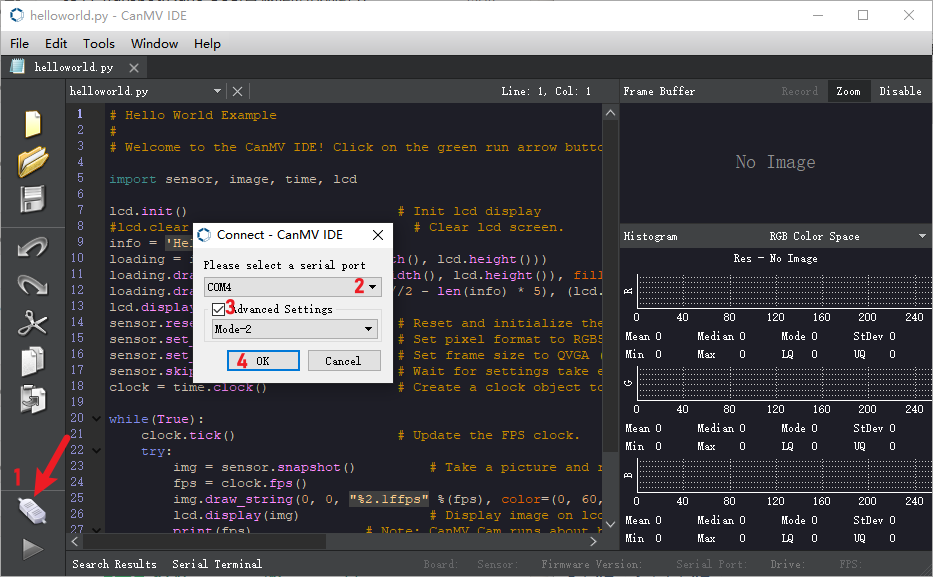
After successful IDE connection, the phenomenon is as follows
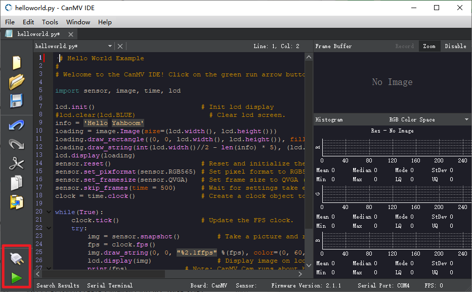
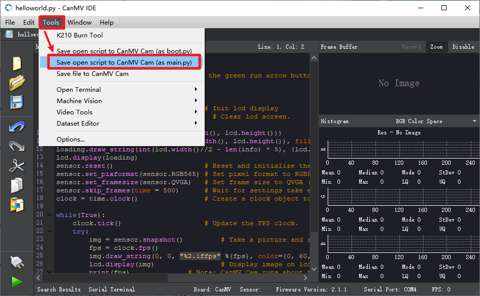
Here we use helloworld.py as an example, open the top menu bar Tools -> Save currently open script as (main.py) to CanMV Cam
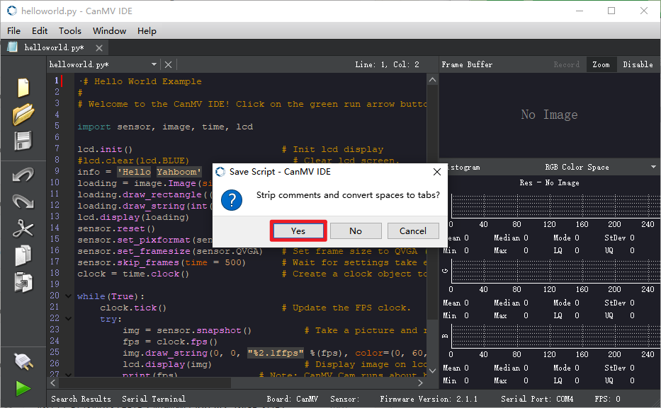
Both Yes/No can be selected here. When the following status appears, the write is successful.
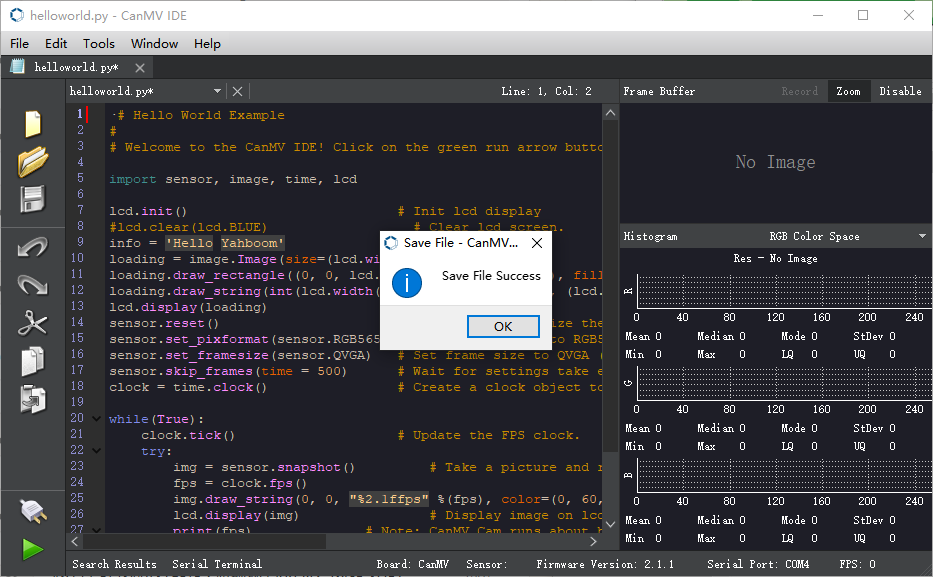
5. Experimental Phenomena
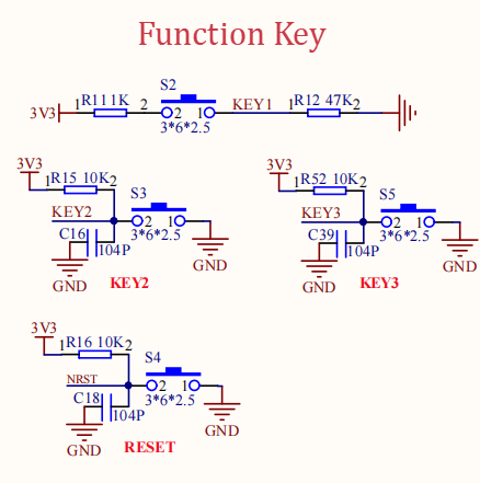
After burning the program, K210 will learn three types of road signs. Use the button on the side closer to the K210 TF card for learning. Collect five samples for each type. After successful collection, the car will move forward. When recognizing the first type of road sign, it will turn right; the second type will turn left; the third type will stop. If using firmware version 2.1.1, the button pin needs to be changed to 17. Please see source code analysis for details