Welcome to MSPM0 Smart Robot Car repository
11. I2C Communication (I2C)
I2C Communication
I2C CommunicationI. Learning ObjectivesII. I2C IntroductionIII. Hardware SetupIV. Environment SetupV. Main FunctionsVI. Experiment Phenomenon
I. Learning Objectives
- Learn and understand basic I2C communication knowledge.
- Learn to drive 0.91-inch OLED LCD screen.
II. I2C Introduction
The I2C bus is a bidirectional two-wire serial bus that provides communication lines between integrated circuits. Its meaning is a protocol for completing information exchange between integrated circuits or functional units.
The I2C module receives and transmits data, and converts data from serial to parallel, or parallel to serial. Interrupts can be enabled or disabled. The interface connects to the I2C bus through data pin (SDA) and clock pin (SCL). It allows connection to standard (up to 100kHz) or fast (up to 400kHz) I2C buses. (Data line SDA and clock SCL form the serial bus, which can send and receive data).
The I2C bus has three types of signals during data transmission: start signal (START), stop (end) signal (STOP), and acknowledge signal (ACK). Secondly, it is in idle state when no data transmission is occurring.
I2C Basic Parameters
Speed: I2C bus has two transmission modes: standard mode (100 kbit/s) and fast mode (400 kbit/s), with faster extended mode and high-speed mode also available for selection.
Device Address: Each device has a unique 7-bit or 10-bit address, and communication can be selected through address selection.
Bus Status: I2C bus has five states: idle state, start signal, end signal, response signal, and data transmission.
Data Format: I2C bus has two data formats: standard format and fast format. Standard format is 8-bit data byte plus 1-bit ack/nack (acknowledge/not acknowledge) bit, fast format allows two bytes to be transmitted simultaneously.
Since SCL and SDA lines are bidirectional, they may also have level errors due to external reasons (such as capacitance in the line, etc.), which can lead to communication errors. Therefore, in I2C bus, pull-up resistors are usually used to ensure that the signal lines are at high level in idle state.
III. Hardware Setup
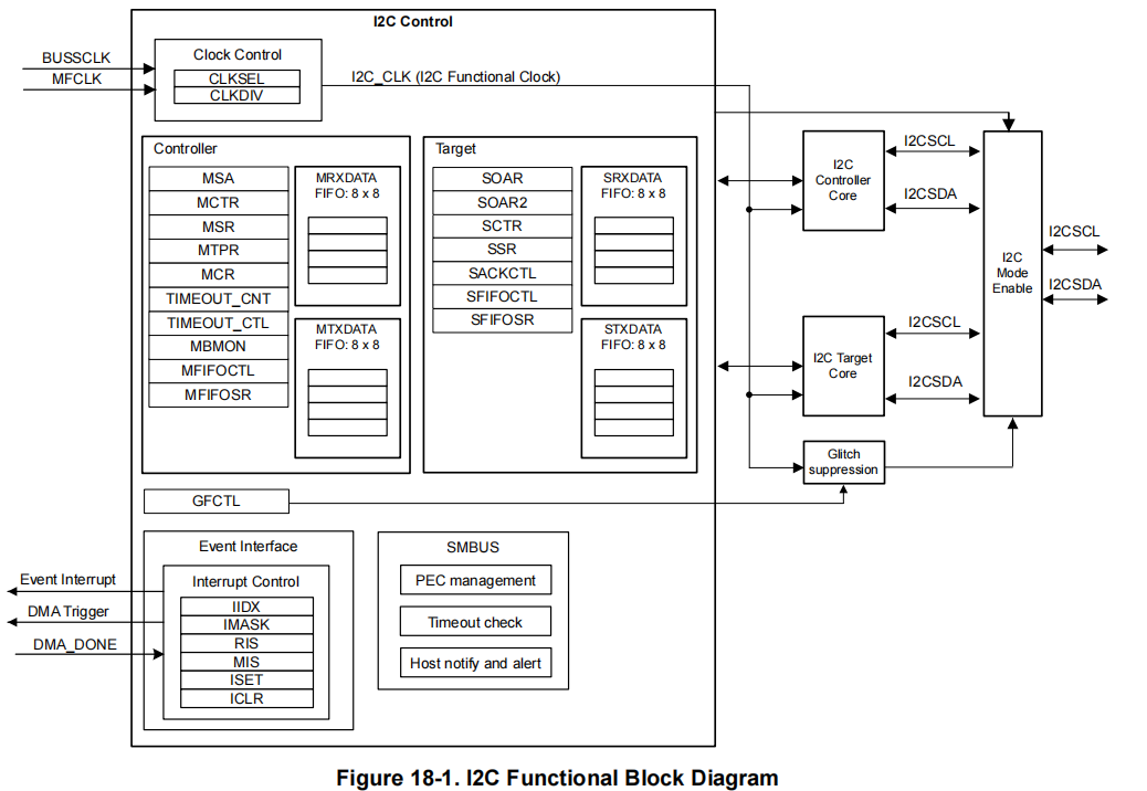
The I2C of MSPM0G series supports master-slave mode, has 7-bit address bits that can be set, supports 100kbps, 400kbps, 1Mbps I2C standard transmission rates, and supports SMBUS. Whether as master or slave, both transmission and reception have independent 8-byte FIFOs. MSPM0 I2C has 8-byte FIFO, generates independent interrupts for controller and target modes, and supports DMA.
Software I2C refers to implementing the I2C communication protocol by writing code in the program. It uses general-purpose input/output (GPIO) pins to simulate the I2C data line (SDA) and clock line (SCL), and transmits data and generates timing signals by controlling the level changes of the pins through software. Compared with hardware I2C, the advantage of software I2C is that it does not require specific hardware support and can be implemented on any microcontroller that supports GPIO functionality. It utilizes the general IO pins of the microcontroller to implement the I2C communication protocol. For software I2C, at least two pins are needed for data line (SDA) and clock line (SCL), and it must be ensured that these pins can meet the timing requirements of the I2C communication protocol. The following is a general pin description:
Data Line (SDA): Pin used for transmitting data. In software I2C, this pin needs to be set to output mode (for master device to send data) and input mode (for master device to receive data). During communication, data transmission needs to be achieved by controlling the level changes of the data line.
Clock Line (SCL): Pin used for the clock signal that controls data transmission. In software I2C, this pin needs to be set to output mode, and clock pulses are generated by controlling the level changes of the clock line to control the transmission of the data line. It should be noted that when selecting appropriate pins, the following aspects should be considered:
- Support input/output configuration: Pins need to support being configured as input or output mode in software and be able to be dynamically switched through programs.
- Hardware limitations and conflicts: Ensure that selected pins are not assigned to other hardware functions or peripherals to avoid conflicts.
- Electrical characteristics: The electrical characteristics of pins should meet the standard requirements of I2C bus, such as correct levels and driving capability.
It should be noted that software I2C implementation requires more program code and computation. Compared with hardware I2C, software I2C is more sensitive in terms of processor efficiency and timing control. Therefore, when selecting pins, processor performance and programmability also need to be considered.
This experiment uses software I2C to drive OLED module to display data.
- I2C Bus Timing Diagram
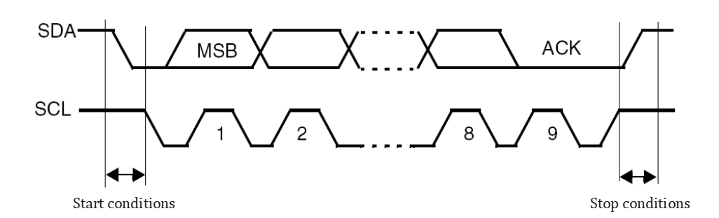
Idle State
SCL high level, SDA high level;
Start Condition
SCL high level, SDA falling edge;
Stop Condition
SCL high level, SDA rising edge;
Data Transmission
SCL low level, SDA rising edge or falling edge;
Acknowledge Signal
After the slave device receives data, it will send a low level to the master device to indicate successful reception;
Data Validity
When the clock line is high level, the data line must remain stable; when the clock line is low level, the data line is allowed to change.
xxxxxxxxxxSCL:High level → Used for start and end of communicationSCL:Low level → Used for sending and ending of data
Hardware Connection
Here our I2C interface has built-in pull-up resistors, so when we connect sensor peripherals, we do not need to connect external pull-up resistors
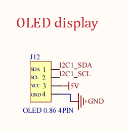
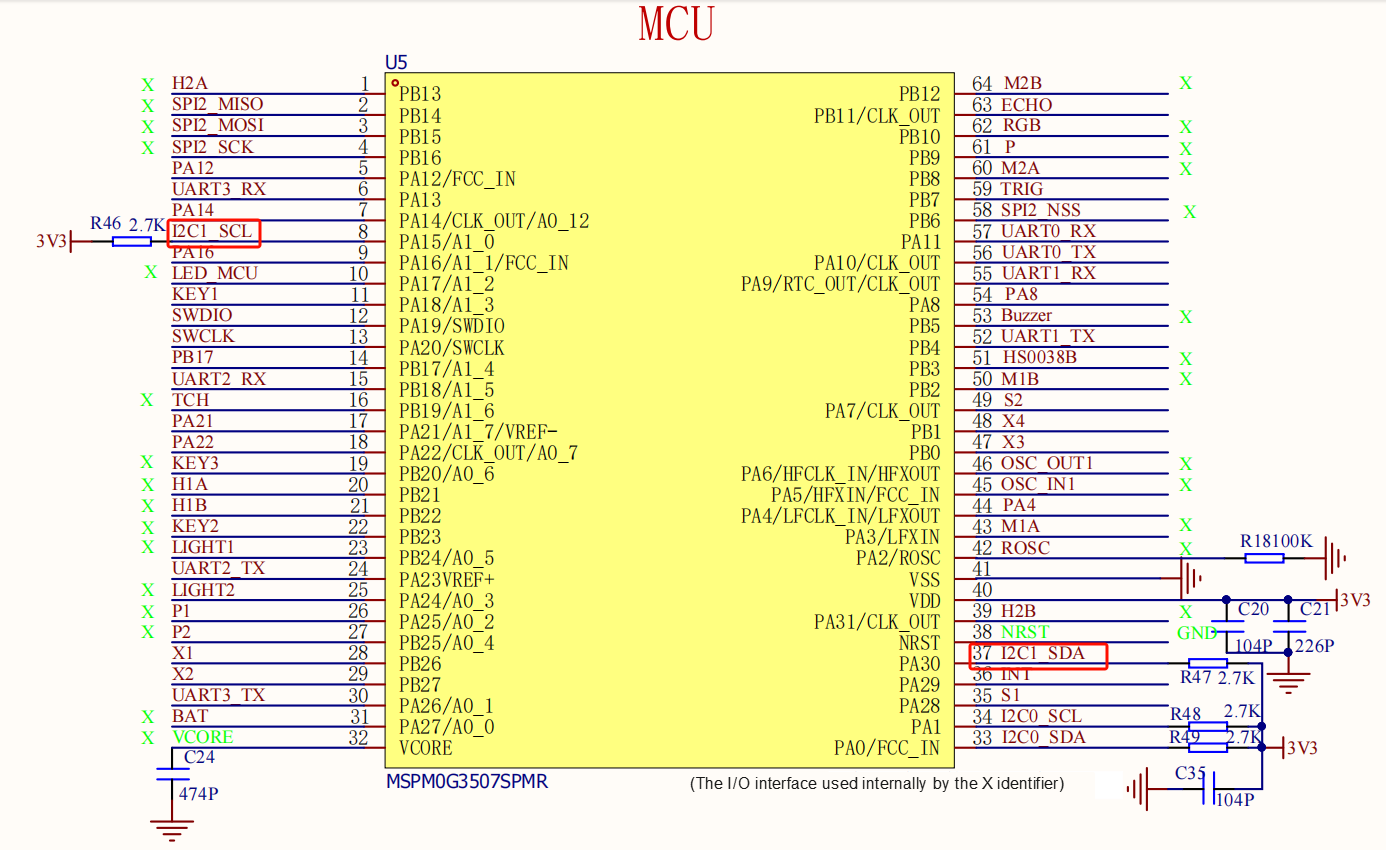
| MSPM0G3507 | 0.91-inch OLED (SSD1306) |
|---|---|
| PA15 | SCL |
| PA30 | SDA |
| 3V3 | VCC |
| GND | GND |
IV. Environment Setup
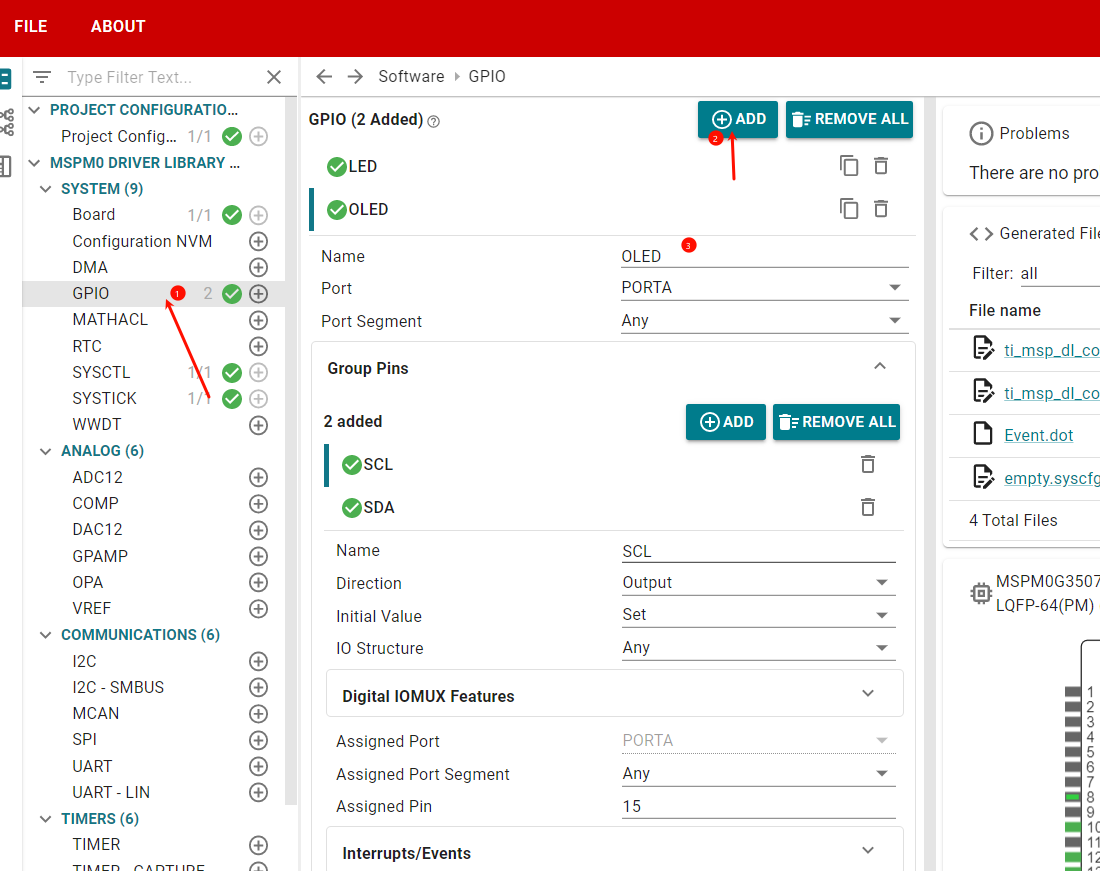
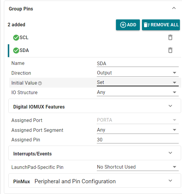
This section's project is based on the LED case for migration and setup. First, we open the graphical configuration through the sysconfig tool to add peripherals
V. Main Functions
Mainly introduces the user-written functional code, for detailed code, you can open the project files we provide and enter the Bsp folder to view the source code.
Function: OLED_Draw_Line
| Function Prototype | void OLED_Draw_Line(char *data, uint8_t line, bool clear, bool refresh) |
|---|---|
| Function Description | Write a line of characters |
| Input Parameter 1 | data: Display data |
| Input Parameter 2 | line: Line number |
| Input Parameter 3 | clear: Clear |
| Input Parameter 4 | refresh: Refresh |
| Return Value | None |
Function: void OLED_ShowNum(u8 x, u8 y, u32 num, u8 len, u8 size1, u8 mode)
| Function Prototype | void OLED_ShowNum(u8 x, u8 y, u32 num, u8 len, u8 size1, u8 mode) |
|---|---|
| Function Description | Display number function Display number at specified position |
| Input Parameters 1, 2 | x,y: Starting coordinates |
| Input Parameter 3 | num: Data length |
| Input Parameter 4 | size1: Font size |
| Input Parameter 5 | mode: 0 inverted display 1 normal display |
| Return Value | None |
Function: void OLED_ShowChar(u8 x, u8 y, u8 chr, u8 size1, u8 mode)
| Function Prototype | void OLED_ShowChar(u8 x, u8 y, u8 chr, u8 size1, u8 mode) |
|---|---|
| Function Description | Display character function Display character at specified position |
| Input Parameters 1, 2 | x,y: Starting coordinates |
| Input Parameter 3 | chr: Character to display |
| Input Parameter 4 | size1: Font size |
| Input Parameter 5 | mode: 0 inverted display 1 normal display |
| Return Value | None |
Function: OLED_ShowString(u8 x, u8 y, u8 *chr, u8 size1, u8 mode)
| Function Prototype | OLED_ShowString(u8 x, u8 y, u8 *chr, u8 size1, u8 mode) |
|---|---|
| Function Description | String display function |
| Input Parameters 1, 2 | x,y: Starting coordinates |
| Input Parameter 3 | Starting address of string to display |
| Input Parameter 4 | size1: Font size |
| Input Parameter 5 | mode: 0 inverted display 1 normal display |
| Return Value | None |
VI. Experiment Phenomenon
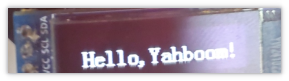
After the program is flashed, the text "Hello,Yahboom!" is displayed on the OLED screen