Welcome to MSPM0 Smart Robot Car repository
1.Voice interaction module communication
Voice interaction module communication
Voice interaction module communicationI. Software-HardwareII. Brief Principles1. Hardware Schematic Diagram2. Introduction to the Voice Interaction Module1. Introduction to the Voice Interaction Module2. Working Principle3. Precautions4. Hardware Interface Description5. Control Principle3. Physical Connection DiagramIII. Main Functions1. User FunctionsIV. Experimental PhenomenaV. Voice Module Firmware Burning
I. Software-Hardware
- KEIL
- MSPM0G3507 Development Board
- Type-C Data Cable or DAP-Link
Download or simulate the program on the development board
- Voice Interaction Integrated Module
II. Brief Principles
1. Hardware Schematic Diagram
.png)
2. Introduction to the Voice Interaction Module
1. Introduction to the Voice Interaction Module
The CI1302 is a new generation of high-performance neural network intelligent voice chip developed by Qiying Tailun. It integrates Qiying Tailun's self-developed brain neural network processor BNPU V3 and CPU core. The system main frequency can reach 220MHz, with a built-in SRAM of up to 640KByte, an integrated PMU power management unit and RC oscillator, and an integrated dual-channel high-performance low-power audio codec. It features multiple peripheral control interfaces including UART, IIC, IIS, PWM, GPIO, and PDM. The chip requires only a few external components such as resistors and capacitors to implement hardware solutions for various intelligent voice products, offering extremely high cost-effectiveness.
Utilizing third-generation hardware BNPU technology, it supports neural networks such as DNN, TDNN, RNN, and CNN, as well as parallel vector operations, enabling functions such as speech recognition, voiceprint recognition, command word self-learning, speech detection, and deep learning noise reduction. This chip solution also supports multiple global languages, including Chinese, English, and Japanese, and can be widely used in home appliances, lighting, toys, wearable devices, industrial products, and automobiles to achieve voice interaction and control, and various intelligent voice solutions.
The CI1302 chip features a Brain Neural Processing Unit (BNPU), supporting offline NN acceleration operations and hardware acceleration for speech signal processing. The CPU clock speed can reach 220MHz, enabling offline far-field speech recognition. It has 2MB of built-in FLASH storage and supports 300 command words.
2. Working Principle
This module uses a voice command wake-up mode. The user needs to say the pre-set wake-up word to activate the voice interaction module. After activation, voice recognition can begin. The default wake-up keyword in the factory firmware is "Hi,yahboom". If no voice is recognized after 20 seconds, the module will enter sleep mode and needs to be woken up again for subsequent use.
When the CI1302 chip recognizes the corresponding voice command, it will send it out via the serial port and IIC interface and provide feedback. The IIC chip stores the received voice command and sends it out via the IIC slave protocol.
The module supports wake-up word modification, command word modification, and custom entries. You can refer to the following tutorials to learn how to operate: AI Voice Interaction Module [2. Modify the wake-up word and command word], [3. Customized protocol entry creation]
3. Precautions
Use 5V power supply. Voltage exceeding 5V will damage the module.
The usage environment should be quiet. Noisy environments will affect recognition performance.
When speaking the words, speak loudly and at a moderate pace. It is recommended to maintain a distance of no more than 5 meters from the module.
4. Hardware Interface Description
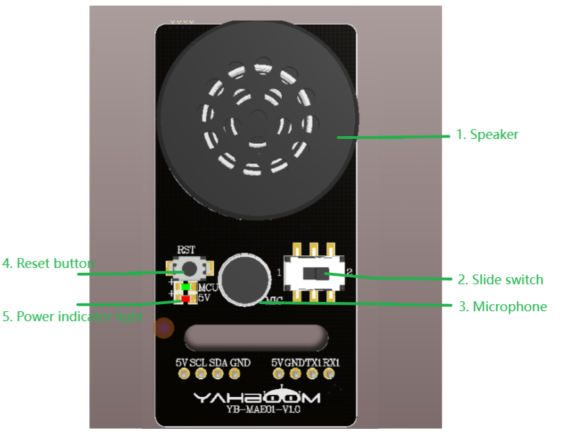
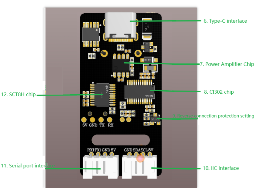
| Number | Hardware Name | Description |
|---|---|---|
| 1 | Speaker | Converts analog signals to sound |
| 2 | Slide Switch | Switches between serial ports for firmware burning |
| 3 | Microphone | Converts sound to analog signals |
| 4 | RST Button | Reset Button |
| 5 | Power Indicator (Red) | Always on when power supply is normal |
| 6 | Type-C Interface | Used for power supply and CI1302 chip/SCT8 firmware update download |
| 7 | Power Amplifier Chip | Converts digital signals into analog signals to drive the speaker |
| 8 | CI1302 Chip | High-performance voice recognition chip, recognizes voice and outputs signals |
| 9 | Reverse Connection Protection | 5V/GND reverse connection protection |
| 10 | IIC Interface | Used as a slave device for power supply and communication with the host device |
| 11 | Serial Port Interface | Provides an external serial port for protocol-controlled playback |
| 12 | STC8H Chip | Converts voice chip commands into IIC protocol commands and serial port commands |
5. Control Principle
| (Schematic Diagram Name) | Control Pin | Specific Meaning |
|---|---|---|
| TX3 | PA26 | Serial Transmitter |
| RX3 | PA13 | Serial Receiver |
Serial Communication:
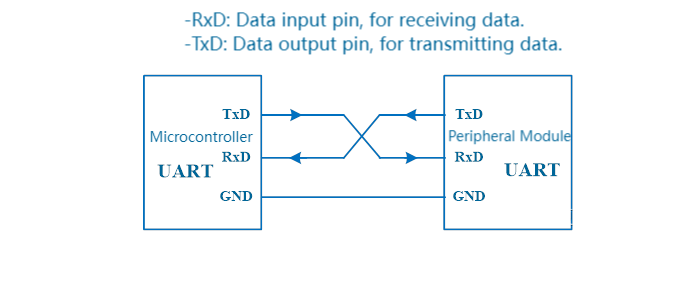
UART (Universal Asynchronous Receiver Transmitter) is a full-duplex universal asynchronous serial transceiver module, mainly used for printing program debugging information, communication between host and slave computers, and ISP program downloading. UART requires at least two data lines for bidirectional simultaneous data transmission between communicating parties. The simplest UART interface consists of three lines: TxD, RxD, and GND. TxD is used for transmitting data, RxD for receiving data, and GND is the ground line. Serial communication between the two chips is achieved through cross-connection.
3. Physical Connection Diagram
.png)
Wiring Pins
Voice Module Wiring (Note: The wiring diagram below is for reference only. Our products come with a dual-ended PH2.0 4-pin all-black cable for the voice module, featuring a foolproof design. No need to worry about wiring issues.)
| Intelligent Voice Interaction Module | MSPM0G3507 |
|---|---|
| RX1 | TX3 |
| TX1 | RX3 |
| GND | GND |
| 5V | 5V |
III. Main Functions
This section mainly introduces the user-written functional code. For detailed code, please open the project file we provided and view the source code in the Bsp folder.
1. User Functions
Function: Write_Data
| Function Prototype | void Write_Data(uint8_t dat) |
|---|---|
| Function Description | Sends data to the voice module |
| Input Parameters | The data frame sent |
| Output Parameters | None |
Function: Processing_Data
| Function Prototype | void Processing_Data(uint8_t RXdata) |
|---|---|
| Function Description | Receives data from the voice module |
| Input Parameters | The data frame received |
| Output Parameters | None |
IV. Experimental Phenomena
- The broadcast content can be selected by modifying the code in the program, as shown in the following images:
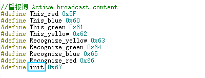
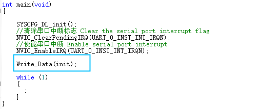
- The broadcast content can be viewed according to the Command word broadcasting word protocol list V3--MSPM0.xlsx file provided in the attachment,
where the first and second bytes AA 55 represents the protocol frame header. The third byte, FF, indicates the broadcast function. The fourth byte is the ID of the broadcast content; here we can see that "I-AM-READY" is hexadecimal 67, so sending 0x67 to register 0x03 in the program will broadcast the corresponding content. The fifth byte is the end frame.

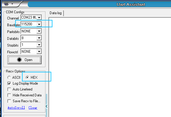
- Open the serial port debugging assistant provided in the attachment, select the corresponding port, and set the baud rate to 115200. Set the receive mode to hexadecimal.
- Open the serial port, say the wake-up word, and after waking up, say "Car lights off". The debugging assistant will then reply with a 0A response.
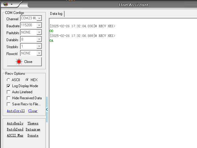
- At this point, you can open the attached Command Word Broadcast Protocol List V3_Chinese file to view the protocol for "Car lights off".

The first and second bytes, AA 55, represent the protocol frame header. The third byte represents the ID of the chip's ten function words. The fourth byte is the command word ID; here, you can see that Car lights off is hexadecimal 0A. The fifth byte is the end frame.
- Speaking other command words will also print the corresponding command word ID in the serial port debugging assistant; you can try them yourself.
V. Voice Module Firmware Burning
xThe voice module needs to be burned into the firmware file CI1302_EN_Single_V00916_UART1_115200_2M(MSPM0).bin provided in the download area. This will enable the intelligent voice interaction module for this car, without the need for multiple burning attempts.
- Download the provided voice module firmware CI1302_EN_Single_V00916_UART1_115200_2M(MSPM0).bin
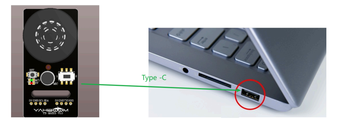
- Connect the voice module's Type-C port to your PC and push the slider on the voice module towards pin 1.
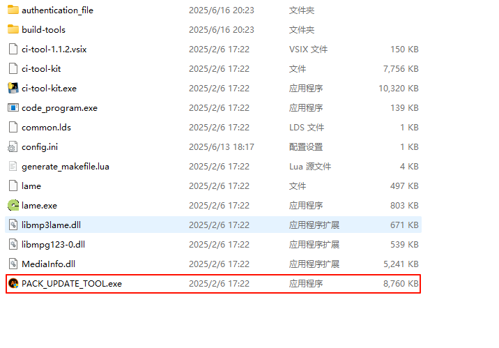
- Open the voice chip firmware flashing tool.
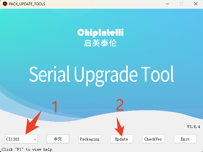
- Select the CI1302 chip and click "Firmware Upgrade".
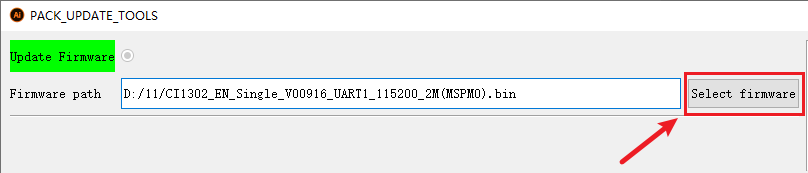
- Locate the factory firmware CI1302_EN_Single_V00916_UART1_115200_2M(MSPM0).bin, select the corresponding firmware
- Go to the corresponding serial port number, baud rate 921600, and check the box next to it.
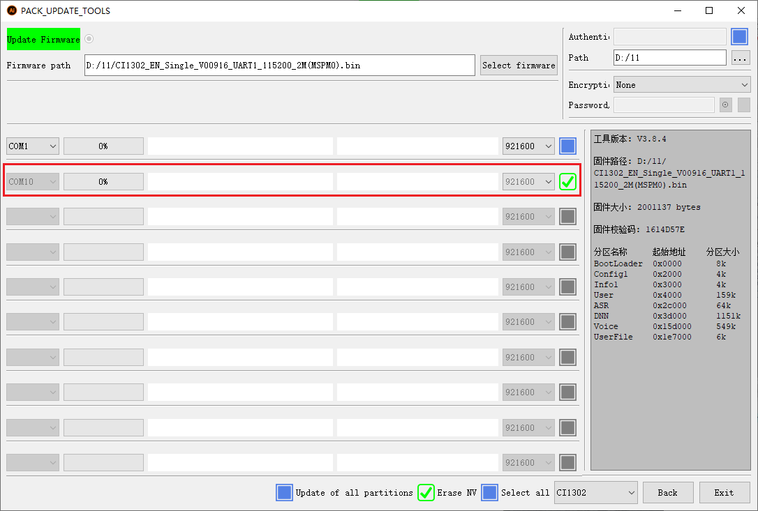
- Press the RST button on the board, and the firmware will be automatically downloaded to the voice module.