Welcome to MSPM0 Smart Robot Car repository
4.K230 color response(Voice)
K230 Color Response (Voice)
K230 Color Response (Voice)I. Software-HardwareII. Brief Principles1. Hardware Schematic Diagram2. Physical Connection Diagram3. Control PrincipleIII. Code AnalysisIV. Voice Module CommandsV. Experimental OperationVI. Experimental Phenomena
This tutorial is a comprehensive experiment combining multiple peripherals. It's recommended to familiarize yourself with individual peripherals first before proceeding with this experiment.
I. Software-Hardware
- KEIL5
- MSPM0G3507 Robot Development Board
k230 Module: External
AI Voice Interaction Integration Module: External
- Type-C Data Cable or DAP-Link
Download or simulate the program on the development board
II. Brief Principles
1. Hardware Schematic Diagram
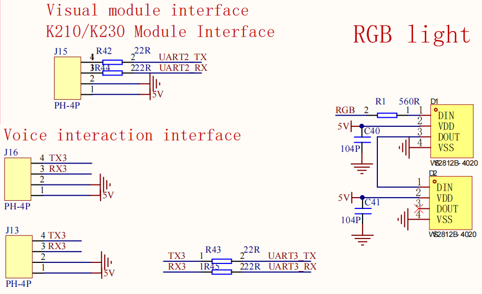
.png)
2. Physical Connection Diagram
.png)
Wire Connection Pins
Motor Wiring (Note: The wiring diagram below is for reference only. We ship with a double-ended PH2.0 6-pin all-black cable with a foolproof design, so there's no need to worry about wiring issues.)
| TT Encoded Motor | MSPM0G3507 |
|---|---|
| M - | M1- |
| M + | M1+ |
| VCC | 3V3 |
| Encoder B | H1B |
| Encoder A | H1A |
| GND | GND |
| TT encoder motor | MSPM0G3507 |
|---|---|
| GND | GND |
| Encoder A | H2A |
| Encoder B | H2B |
| VCC | 3V3 |
| M + | M2+ |
| M - | M2- |
Voice module wiring (Note: The wiring diagram below is for reference only. Our products come with a dual-ended PH2.0 4-pin all-black voice module cable with a foolproof design; no wiring issues are necessary.)
| Intelligent voice interaction module | MSPM0G3507 |
|---|---|
| RX1 | TX3 |
| TX1 | RX3 |
| GND | GND |
| 5V | 5V |
K230 Wiring (Note: The wiring diagram below is for reference only. Our products come with a K230 double-ended PH2.0 4-pin all-black cable with a foolproof design; you don't need to worry about wiring issues.)
| K230 | MSPM0G3507 |
|---|---|
| RX | TX2 |
| TX | RX2 |
| GND | GND |
| 5V | 5V |
3. Control Principle
- Program Flowchart

Control Principle:
| Module | Function |
|---|---|
| K230 Vision Module | Select the color block you want to recognize, and then send the data to the microcontroller via serial port |
Communication Protocol:
When the K230 recognizes the color block you need to recognize, it will send a data frame via serial port, with the following format:
| Experimental Routine | Start Character | Length | Separator | Routine Number | Separator | x | Separator | y | Separator | w | Separator | h | End Character |
|---|---|---|---|---|---|---|---|---|---|---|---|---|---|
| Color Recognition | $ | XX | , | 01 | , | XXX | , | XXX | , | XXX | , | XXX | # |
Microcontroller Part:
Receives data sent by the K230 via serial port and processes each byte of data. Extracts valid data from the data frame content and stores it in an array. The processed data is then retrieved to control the car and achieve the desired effect.
III. Code Analysis
Main Function Analysis
Function: Pto_Loop
| Function Prototype | void Pto_Loop(void) |
|---|---|
| Function Description | Main function for running the program |
| Input Parameters | None |
| Output Parameters | None |
Partial Function Analysis
- main.c
ColorMode color_mode = 1; // 1: Patrol, 2: Trackingint main(void){ bsp_init();// Required peripheral initialization Control_RGB_ALL(OFF);//Turn off RGB delay_ms(100); OLED_ShowString(0,0,"pid_output:",8,1);//The PID output is used to control left and right. OLED_ShowString(0,20,"pid_output1:",8,1);//The PID output is displayed to control the front and rear. OLED_Refresh(); while (1) { Pto_Loop(); OLED_ShowSNum(75,0, pid_output, 3, 8, 1); OLED_ShowSNum(75,20,pid_output1,3,8,1); OLED_Refresh(); }}BSP_init: Hardware initialization
pto__Loop: Continuously processes received K230 messages.
- yb_protocol.c
/** * @Brief: Data analysis * @Note: * @Parm: Pass in a received data frame and length * @Retval: */void Pto_Data_Parse(uint8_t *data_buf, uint8_t num){ uint8_t pto_head = data_buf[0]; uint8_t pto_tail = data_buf[num-1]; // Check head and tail if (!(pto_head == PTO_HEAD && pto_tail == PTO_TAIL)) { //DEBUG_PRINT("pto error:pto_head=0x%02x , pto_tail=0x%02x\n", pto_head, pto_tail); return; } uint8_t data_index = 1; uint8_t field_index[PTO_BUF_LEN_MAX] = {0}; int i = 0; int values[PTO_BUF_LEN_MAX] = {0}; char msgs[][PTO_BUF_LEN_MAX] = {0}; // Split Field for (i = 1; i < num-1; i++) { if (data_buf[i] == ',') { data_buf[i] = 0; field_index[data_index] = i; data_index++; } } // Parsing length and function ID for (i = 0; i < 2; i++) { values[i] = Pto_Char_To_Int((char*)data_buf+field_index[i]+1); } uint8_t pto_len = values[0]; uint8_t pto_id = values[1]; ParseCommonFields(pto_id,data_buf,pto_len,field_index,data_index,values,msgs);}The received data conforming to the protocol is parsed to obtain the function ID number and the data information carried in the data, and the corresponding function processing function is executed. This project uses metadata parsing. The core idea is to separate the description of the protocol format (field position, type, etc.) from the parsing logic, define the protocol format through data structures (such as structure arrays), and the parsing function automatically processes the data according to these descriptions.
The protocol can also parse out data of different types. If you want to know the implementation details, you can study it yourself. I will not explain too much. This function has been adapted to all K230 communication protocols in this store. You can use it normally without fully understanding it.
- bsp_K230_control.c
void Color_Rec(const char* msg){ if(strcmp(msg,"RED")==0) { Write_Data(0x0B); Control_RGB_ALL(Red_RGB); delay_ms(100); } else if(strcmp(msg,"GREEN")==0) { Write_Data(0x0C); Control_RGB_ALL(Green_RGB); delay_ms(100); } else if (strcmp(msg, "BLUE")==0) { Write_Data(0x0D); Control_RGB_ALL(Blue_RGB); delay_ms(100); } else if (strcmp(msg, "YELLOW")==0){ Write_Data(0x0E); Control_RGB_ALL(Yellow_RGB); delay_ms(100); }}Color_Rec: Controls the RGB lights to illuminate and then transmits the data to the voice module, thereby controlling the voice module to make a broadcast.
IV. Voice Module Commands
| 命令词 (Command Word) | 功能类型 (Function Type) | 播报语句 (Broadcast Statement) | 播报模式 (Broadcast Mode) | 发送协议 (Send Protocol) | 接收协议 (Receive Protocol) |
|---|---|---|---|---|---|
| WELCOME | 欢迎语 (Welcome) | welcome | 被 (Passive) | AA 55 01 00 FB | AA 55 01 00 FB |
| BYE | 休息语 (Rest) | bye | 主 (Active) | AA 55 02 6F FB | AA 55 02 00 FB |
| HI-YAHBOOM | 唤醒词 (Wake Word) | I am here | 主 (Active) | AA 55 03 00 FB | AA 55 03 00 FB |
| VOLUME-UP | 增大音量 (Increase Vol) | Volume Up | 主 (Active) | AA 55 04 00 FB | AA 55 04 00 FB |
| VOLUME-DOWN | 减小音量 (Decrease Vol) | Volume down | 主 (Active) | AA 55 05 00 FB | AA 55 05 00 FB |
| MAX-VOLUME | 最大音量 (Max Volume) | Maximum volume | 主 (Active) | AA 55 06 00 FB | AA 55 06 00 FB |
| MID-VOLUME | 中等音量 (Medium Volume) | Medium volume | 主 (Active) | AA 55 07 00 FB | AA 55 07 00 FB |
| MINI-VOLUME | 最小音量 (Min Volume) | Minimum Volume | 主 (Active) | AA 55 08 00 FB | AA 55 08 00 FB |
| START-REPORT | 开播报 (Enable Broadcast) | Start broadcasting | 主 (Active) | AA 55 09 00 FB | AA 55 09 00 FB |
| STOPT-REPORT | 关播报 (Disable Broadcast) | Stop Broadcast | 主 (Active) | AA 55 0A 00 FB | AA 55 0A 00 FB |
| RED-LIGHT-UP | 命令词 (Command Word) | ok red light is on | 主 (Active) | AA 55 00 0B FB | AA 55 00 0B FB |
| GREEN-LIGHT-UP | 命令词 (Command word) | ok green light is on | 主 (Active) | AA 55 00 0C FB | AA 55 00 0C FB |
| BLUE-LIGHT-UP | 命令词 (Command word) | ok blue light is on | 主 (Active) | AA 55 00 0D FB | AA 55 00 0D FB |
| YELLOW-LIGHT-UP | 命令词 (Command word) | ok yellow light is on | 主 (Active) | AA 55 00 0E FB | AA 55 00 0E FB |
V. Experimental Operation
- Connect the wires according to the hardware wiring instructions in the tutorial.
- Open the project used by MSPM0G3507, then compile and flash it, and finally reset or power on again.
- Place
Color_Rec.pyin the root directory of the K230's SD card and rename it tomain.py. Then reset or power cycle the device. If you are unsure how to program the K230, please refer to the K230 quick start tutorial. - Place the color block in front of the vehicle, adjust the K230 module bracket to the appropriate angle, and connect the power supply.
- After successful initialization, the K230 will begin recognizing the preset colors. Press the vehicle reset button and wait three seconds for the vehicle to respond.
Note: The voice module requires firmware flashing in advance.
Voice Module Firmware Flashing
xxxxxxxxxxSimply burn the CI1302_EN_Single_V00916_UART1_115200_2M(MSPM0).bin file we provide to implement all the related cases of the intelligent voice interaction module for this car. For firmware burning, please refer to [Chapter 8: Extended application course (Sold separately) → 1.Voice interaction module communication]. If it has been burned before, it does not need to be burned again.
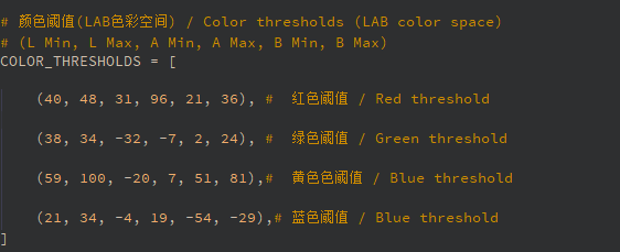
Color_Rec.py provides recognition of four preset colors: red, green, blue, and yellow. If the recognition effect is unsatisfactory, refer to the K230 color recognition tutorial to learn how to change the LAB threshold to one suitable for your environment.
VI. Experimental Phenomena
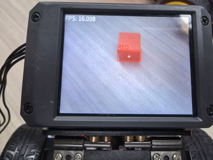
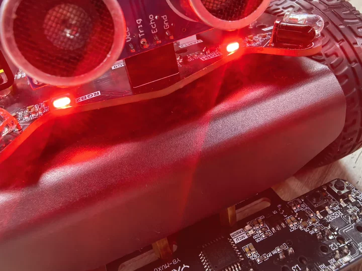
Turn on the power switch, wait for system initialization to complete, the screen will display the camera feed. Place the color block within the detection range, and it will frame the color you want to recognize. After three seconds, when a color with the corresponding threshold appears within the camera range, the car will start responding to the specified color.
Note: Only red, blue, green, and yellow colors can be recognized and responded to. When connecting our AI voice interaction integration module, there will be voice broadcast when detecting specified colors. Users who have not purchased the voice module don't need to worry. When the voice module is not connected, the K230 can still implement this case, just without the voice broadcast function.