Welcome to MSPM0 Smart Robot Car repository
6.1 Infrared line tracking sensor-8 channel infrared tracking sensor module
8-Channel Line Tracking Module
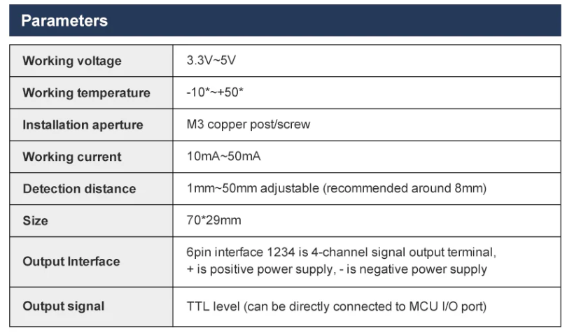
2.1 Basic Parameters
8-Channel Module Calibration Operation Steps
- First, power on the module and wait at least 20s. The main purpose is to let the probe stabilize. (Need to wait every time when powering on)
- If it's the first time powering on and hasn't been calibrated, the module's red light will keep flashing. (At this time, you need to enter calibration mode)
- Long press the onboard key1 button, wait for the board's red light to stay constantly lit, and enter calibration mode. Friendly Reminder: After entering calibration mode, the lights on the probe will no longer react to black and white lines, meaning they are not effective. Wait for calibration to complete before they will react.
- Place the probe according to your usage height (calibrate at the height where it will run), place the entire probe on the black line, stop for 3 seconds and wait for data to stabilize (do not move the probe during this period), as shown in the figure
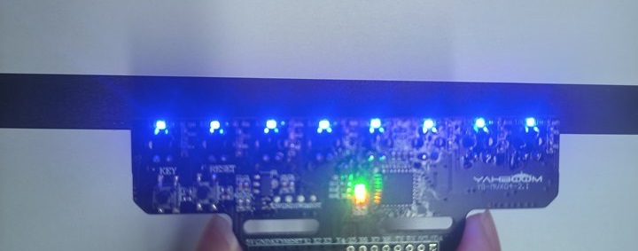
- After 3s, lightly press the key1 button to record the value of the probe detecting the black line. After recording is complete, the board's red light will flash quickly, then return to constant lighting.
- Then, place the probe on the white line, stop for 3 seconds and wait for data to stabilize (do not move the probe during this period), as shown in the figure
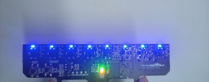
- After 3s, lightly press the key1 button to record the value of the probe detecting the white line. After recording is complete, the board's red light will flash quickly.
- If calibration is successful, the onboard red light will turn off and enter detection mode; if it fails, the onboard red light will keep flashing slowly, at which time you need to recalibrate.
If you accidentally enter calibration mode, you can press the reset button to reset the module or quickly double-click the key1 button to exit calibration.
The calibrated values are saved after power-off each time, and can be used directly next time you power on, without needing to calibrate every time you power on. Unless you change to a different environment and height, at which time you need to recalibrate.
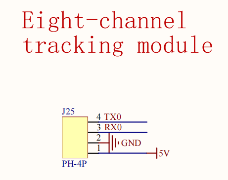
2.2 Hardware Wiring
| Eight-Channel Line Tracking Module | MSPM0G3507 |
|---|---|
| 5V | 5V |
| GND | GND |
| TX | RX0 |
| RX | TX0 |
.png)
.png)
2.3 Environment Setup
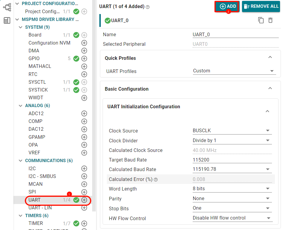
Open sysconfig tool and configure the following
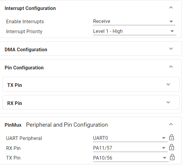
Open receive interrupt pin configuration as follows
2.4 Partial Code Analysis
bsp_ir.c
xvoid IRDataAnalysis(void){ ... // If no data received or data reception not complete, do not process if (IR_recv_complete_flag == 0) return; // Disable interrupt to prevent receiving new data during parsing __disable_irq(); // Find the first '$' of the format header while ((IR_recv_buff[head] != '$') && (head < IR_recv_length)) { head++; } if (head == IR_recv_length) { // Data header not found, clear receive flag, wait for next reception IR_recv_complete_flag = 0; IR_recv_length = 0; __enable_irq(); return; } // Set valid data start address buff = &IR_recv_buff[head]; // Find the end '#' while ((buff[end] != '#') && (end < IR_recv_length)) { end++; } if ((head + end) == IR_recv_length) { // Data end not found, clear receive flag, wait for next reception IR_recv_complete_flag = 0; IR_recv_length = 0; __enable_irq(); return; } // Copy data to temp buffer if (end + 1 < sizeof(temp)) { strncpy(temp, buff, end + 1); temp[end + 1] = '\0'; // Ensure string termination // Check if data format is correct ($D,...) if (temp[0] == '$' && temp[1] == 'D') { char *token = strtok(temp, ","); int index = 0; while (token != NULL && index < IR_Num) { // Parse x1:1, x2:1, ..., x8:1 format data if (strstr(token, "x") != NULL) { char *colon = strchr(token, ':'); if (colon != NULL) { // Extract numeric characters after ':' and convert to value IR_Data_number[index] = (colon[1] - '0'); index++; } } token = strtok(NULL, ","); } } } // Clear receive complete flag, reset buffer, wait for next reception IR_recv_complete_flag = 0; IR_recv_length = 0; memset(IR_recv_buff, 0, USART_RECEIVE_LENGTH); __enable_irq(); }// Continuously receive sensor returned data in serial port interrupt, then determine every 20ms in timer interrupt whether frame end is received, close interrupt to process new data when frame end is receivedvoid UART_0_INST_IRQHandler(void){ uint8_t RecvDATA = 0; // Check interrupt source switch (DL_UART_getPendingInterrupt(UART_0_INST)) { case DL_UART_IIDX_RX: RecvDATA = DL_UART_Main_receiveData(UART_0_INST); // Check if buffer is full if (IR_recv_length >= USART_RECEIVE_LENGTH - 1) { // Buffer full, reset receive state (discard data) IR_recv_complete_flag = 0; IR_recv_length = 0; break; } // Store received data to buffer IR_recv_buff[IR_recv_length++] = RecvDATA; IR_recv_buff[IR_recv_length] = '\0'; // Mark reception complete when '#' is received if (RecvDATA == '#') { IR_recv_complete_flag = 1; } break; default: break; }}2.5 Main Functions
IRDataAnalysis
| Function Prototype | void IRDataAnalysis(void) |
|---|---|
| Function Description | Infrared data parsing function, used to parse received infrared sensor data. The process includes: checking data reception complete flag, finding data header ('$') and data tail ('#'), verifying data format (must start with "$D"), parsing "x1:1,x2:1,...x8:1" format 8-channel sensor data and storing to IR_Data_number array, finally resetting receive state to wait for next data |
| Input Parameters | None |
| Return Value | None |
2.6 Experimental Phenomenon
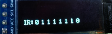
Connect the car wires, connect the OLED module, after burning the program to MSPM0, sensor data is displayed on the OLED