yahboom
HomeLearn
Solution
Blog
Online Store
About Us
EN/中文
MSPM0 Smart Robot Car📖
1.Quick Start Guide
  • 1. Assembly Videos
  • 2. Quick Start Videos
  • 3. Battery charging
  • 4. Notes
2.Introduction to the MSPM0 Car
  • 1.About MSPM0
  • 2.Development board interface description
3.Development environment setup and usage
  • 1.CCS Theia development
  • 2.MDK Arm development
  • 3.Uniflash burning
  • 4.External crystal oscillator configuration
  • 5.Project Migration
4.MSPM0 basic course
  • 1. LED light control (GPIO)
  • 2. Buzzer Control (GPIO)
  • 3. Button Control (EXTI)
  • 4. Serial Port (UART)
  • 5. Voltage Detection (ADC)
  • 6. Temperature Detection (ADC)
  • 7. Independent Watchdog (WWDG)
  • 8. Window Watchdog (WWDG)
  • 9. Timer (TIM)
  • 10. Breathing LED (PWM)
  • 11. I2C Communication (I2C)
  • 12. External Flash (SPI)
  • 13. Internal Flash (Flash)
  • 14. DMA
  • 15. FreeRTOS
5.Sensor basic course
  • 1.Servo control
  • 2.Ultrasonic servo PTZ basic use
  • 3.Motor PID control
  • 4.OLED display photosensitive value
  • 5.Infrared avoid sensor
  • 6.1 Infrared line tracking sensor-8 channel infrared tracking sensor module
  • 6.2 Infrared line tracking sensor-4 channel infrared tracking sensor module
  • 7.Infrared remote control
  • 8.Ultrasonic ranging
  • 9.RGB light drive
  • 10.MPU6050 raw data acquisition
  • 11.MPU6050 data fusion
  • 12.K210 vision recognition module
  • 13.K230 vision recognition module
6.Smart car course
  • 1.1 Car line tracking-8 channel infrared tracking sensor module
  • 1.2 Car line tracking-4 channel infrared tracking sensor module
  • 2.1 Drawing a circle-8 channel infrared tracking sensor module
  • 2.2 Drawing a circle-4 channel infrared tracking sensor module
  • 3.Ultrasonic following
  • 4.Ultrasonic avoid
  • 5.Ultrasonic avoid(Servo PTZ)
  • 6.Infrared sensor avoid
  • 7.Light following
  • 8.Gyroscope calibration straight-line walk
  • 9.Infrared remote control
  • 10.Autonomous driving car
7.Vision application course
  • 1.K210 autonomous driving
  • 2.K210 color tracking
  • 3.K210 handwritten digit action
  • 4.K210 color response
  • 5.K210 road sign indication action
  • 6.K210 following machine code
  • 7.K210 QR code command
  • 8.K230 vision line tracking
  • 9.K230 color tracking
  • 10.K230 machine code tracking
  • 11.K230 QR code command
  • 12.K230 autonomous avoid
  • 13.K230 license plate tracking
  • 14.K230 face tracking
  • 15.K230 gaze direction tracking
  • 16.K230 palm tracking
  • 17.K230 target tracking
  • 18.K230 human body tracking
  • 19.K230 OCR character recognition
8.Extended application course (Sold separately)
  • 1.Voice interaction module communication
  • 2.Voice interaction control
  • 3.K230 road sign indication action(Voice)
  • 4.K230 color response(Voice)
  • 5.K230 gesture control(Voice)
  • 6.K230 rock-paper-scissors(Voice)
  • 7.8-channel grayscale color line tracking
  • 8.Bluetooth remote control
  • 9.K210 Scenario-based autonomous driving
  • 10.K230 Scenario-based autonomous driving
Download
  • Code
  • SCH
  • 3D Model File
  • MSPM0 Data Sheet
  • Voice firmware
  • Hardware interface manual
Download ZIP

Welcome to MSPM0 Smart Robot Car repository

2.2 Drawing a circle-4 channel infrared tracking sensor module

Drawing a Circle - 4 Channel Infrared Tracking Sensor Module

Drawing a Circle - 4 Channel Infrared Tracking Sensor Module1. Hardware Connection2. Partial Code Analysis3. Main Functions4. Experimental Phenomenon


1. Hardware Connection

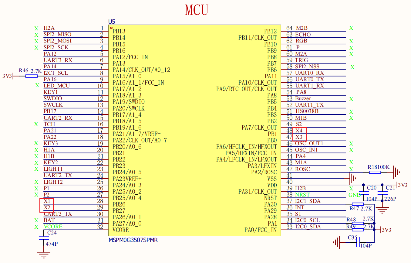
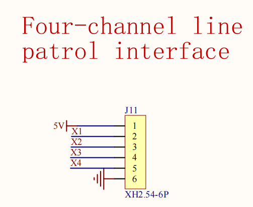
4 Channel Infrared Tracking Sensor ModuleMSPM0G3507
5V5V
GNDGND
X1X1
X2X2
X3X3
X4X4

启动小车 (15)

PixPin_2025-11-05_12-08-33

image-20251028220253456

2. Partial Code Analysis

Control Principle

Car Head Left
Car Head Right
Car Head Out of Line
Start
Get 4-channel line tracking data
Display sensor status
Car Head Direction
Turn Right
Turn Left
Reverse and Turn Handling
Motor Control


Four_linewalking.c

​x
//带死区处理的位置式PID / Positional PID with dead zone processing 
float APP_IR_PID_Calc(int8_t actual_value)
{
​
    float IRTrackTurn = 0;
    int8_t error;
    static int8_t error_last=0;
    static float IRTrack_Integral;//积分 / Integral   
    
    error=actual_value;
    
    IRTrack_Integral +=error;
    
    //位置式pid / Positional PID
    IRTrackTurn=error*IRTrack_Trun_KP
                            +IRTrack_Trun_KI*IRTrack_Integral
                            +(error - error_last)*IRTrack_Trun_KD;
    
​
​
    if (IRTrackTurn > (MAX_SPEED - MOTOR_DEAD_ZONE))
            IRTrackTurn = (MAX_SPEED - MOTOR_DEAD_ZONE);
    if (IRTrackTurn < (MOTOR_DEAD_ZONE - MAX_SPEED))
            IRTrackTurn = (MOTOR_DEAD_ZONE - MAX_SPEED);
    return IRTrackTurn;
}
//得到四路循迹模块的数据 / Get data from 4-channel line tracking module
void Four_GetLineWalking(int *LineL1, int *LineL2, int *LineR1, int *LineR2)
{
    *LineL1 = LineWalk_L1_IN;
    *LineL2 = LineWalk_L2_IN;
    *LineR1 = LineWalk_R1_IN;
    *LineR2 = LineWalk_R2_IN;
}
//画地为牢循迹反逻辑 / Drawing a circle line tracking reverse logic
void LineWalking(void)
{
    int8_t err = 0;
        Four_GetLineWalking(&LineL1, &LineL2, &LineR1, &LineR2);//获取黑线检测状态 / Get black line detection status
        if(LineL1 ==0 && LineR1 ==0)
        {
             err =70;
            // 应用PID控制 这里根据实际情况调节 / Apply PID control, adjust according to actual situation here
            pid_output_IRR = (int)(APP_IR_PID_Calc(
            -err));
             Motion_Car_Control(-IRR_SPEED, 0, pid_output_IRR);
             delay_ms(400);
            return ;
        }
    else if(LineL2 == 0 && LineR2 == 1) err = -30;    // 左传感器检测到黑线,右传感器未检测到黑线 / Left sensor detects black line, right sensor does not detect black line
        else if(LineL2 == 0 && LineL1 == 0) err = -40;    // 左传感器和中间传感器都检测到黑线 / Left sensor and middle sensor both detect black line
​
        else if(LineR2 == 0) err = 30; // 右传感器检测到黑线 / Right sensor detects black line
        else if(LineR2 == 0 && LineR1 == 0) err = 40;   // 右传感器和中间传感器都检测到黑线 / Right sensor and middle sensor both detect black line
        else if(LineL2 == 1 && LineR2 == 1) err = 0; // 两侧传感器都未检测到黑线 / Both left and right sensors do not detect black line
        else err = 0;
​
    // 应用PID控制 / Apply PID control
    pid_output_IRR = (int)(APP_IR_PID_Calc(
            -err));
    
    // 控制小车运动 / Control car movement 
    Motion_Car_Control(IRR_SPEED, 0, pid_output_IRR);
    
}

3. Main Functions

LineWalking

Function Prototypevoid LineWalking(void)
Function DescriptionFour-sensor line tracking control based on "drawing a circle" logic: gets four-sensor status, calculates deviation value err based on different detection conditions. When LineL1 and LineR1 both detect black lines, triggers special control (reverse speed + PID adjustment with delay); other conditions set err based on left/right sensor status, controls car movement after PID calculation (straight line speed is IRR_SPEED)
Input ParametersNone
Return ValueNone

4. Experimental Phenomenon

After connecting the car properly, connecting the OLED module, and burning the program to MSPM0, place the car on a white background with black lines map, the car will move in a circular pattern within the bounded area, and sensor data will be displayed on the OLED

Where L2, L1, R1, R2 represent the four sensor data from left to right
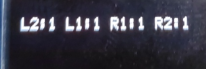
image-20251028201826877

Drawing a circle-8 channel infrared tracking sensor module
Ultrasonic following

COMPANY

  • About us
  • Team Style
  • Blog

LEARNING & EXPLORATION

  • Tutorials
  • Edge AI hardware
  • Educational robots
  • Embedded intelligent hardware

WHERE TO BUY

  • Yahboom Online Store
  • Amazon
  • Alibaba
  • AliExpress
  • Mercado

TECHNOLOGY SUPPORT

  • Email: support@yahboom.com

BE A DISTRIBUTOR

  • Email: sales@yahboom.com
QR Code
QR Code

Copyright © 2017-2026 Yahboom. All Rights Reserved.

EN/中文