Welcome to MSPM0 Smart Robot Car repository
12.K210 vision recognition module
K210 Vision Module
K210 Vision Module2.1 Serial Communication2.2 k210 Vision Module2.3 Hardware Connection2.4 Environment Setup2.5 Partial Code Explanation2.6 Main Functions2.7 K210 Program Burning2.8 Experimental Phenomenon
2.1 Serial Communication
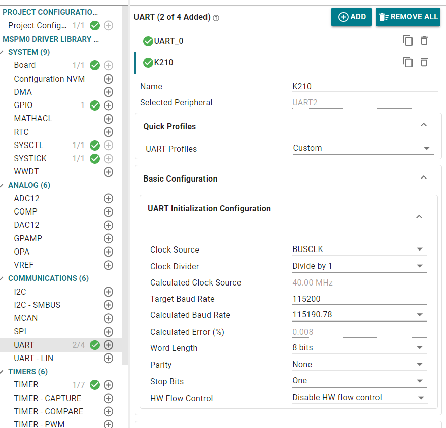
USART: Universal Synchronous/Asynchronous Receiver/Transmitter. It can automatically generate data frame timing based on one byte of data from the data register and send it out through the TX pin, or automatically receive data frame timing from the RX pin and concatenate it into one byte of data, stored in the data register. This experiment uses UART2.
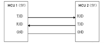
When using serial port for communication, both communication parties must be on the "same channel". "Same channel" means the same communication protocol. Serial port (USART) stipulates: data must be transmitted in the form of "frames" during communication. One frame of serial port data includes: start bit + data bit + parity bit + stop bit. Where: 1) Start bit: fixed is 1 cycle low level signal 2) Data bit: can be agreed by both parties as 5 ~ 9 bits 3) Parity bit: serial port uses parity check, can be agreed by both parties 4) Stop bit: optional 0.5 ~ 2 cycles high level. At the same time, to synchronize the transmission speed of both parties, it is also necessary to agree on the number of data frames transmitted per second, called baud rate. Typical baud rates include 9600, 115200, 57600...
2.2 k210 Vision Module
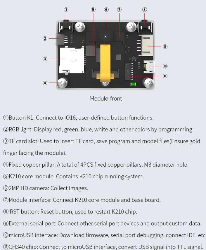
Kanzhi K210 is a system-on-chip that integrates machine vision and machine hearing capabilities. It uses TSMC's ultra-low power 28nm advanced process, has a dual-core 64-bit processor with total computing power up to 1TOPS, built-in various hardware acceleration units (KPU, FPU, FFT, etc.), and has good power performance, stability and reliability.
Function distribution is as follows:
2.3 Hardware Connection
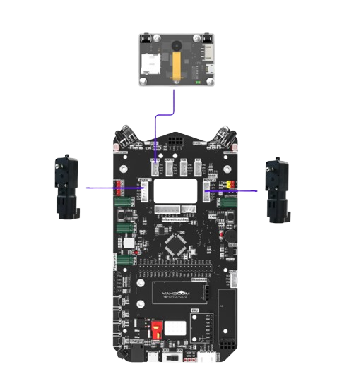
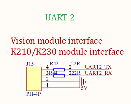
| K210 Vision Module | MSPM0G3507 |
|---|---|
| 5V | 5V |
| GND | GND |
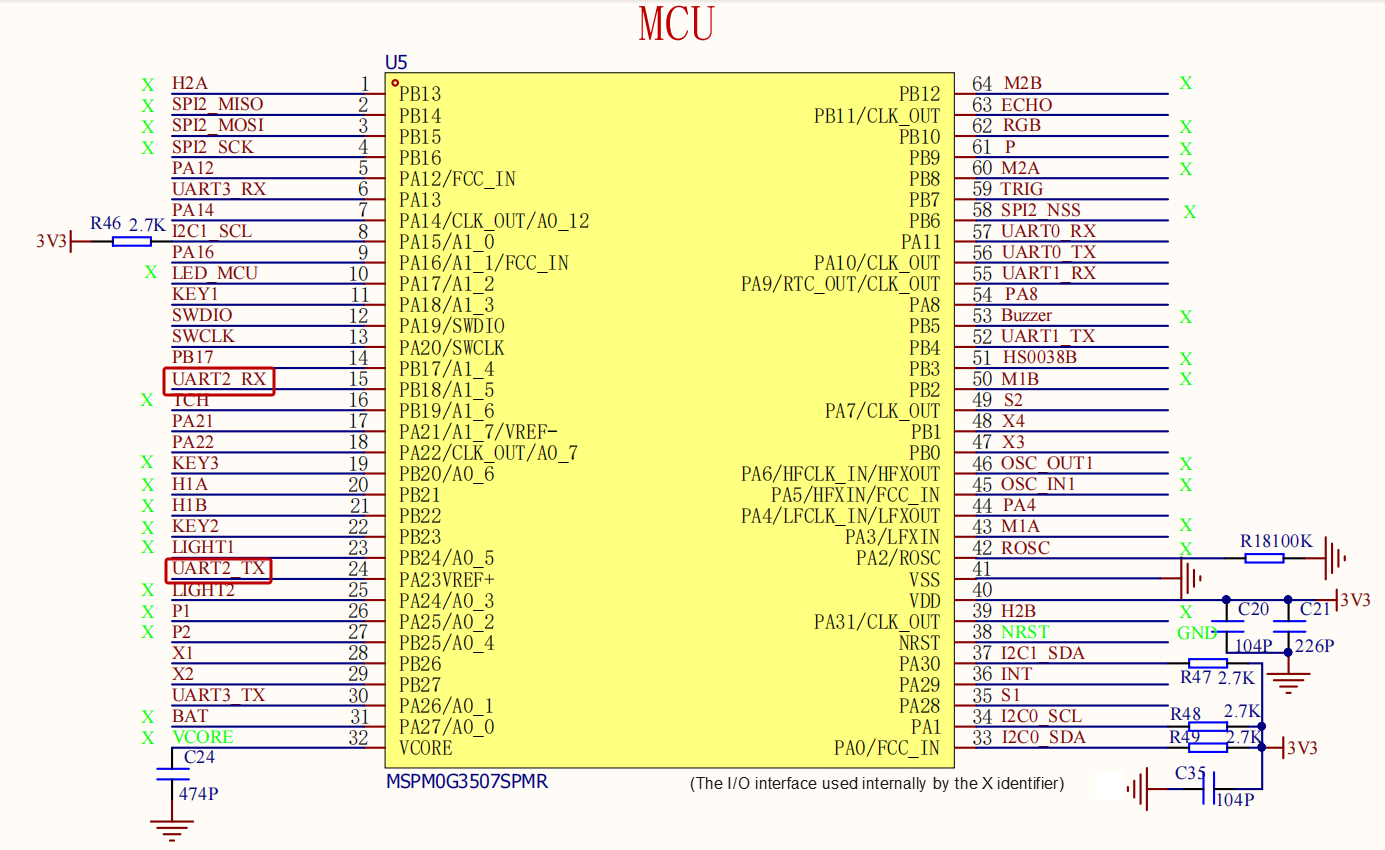
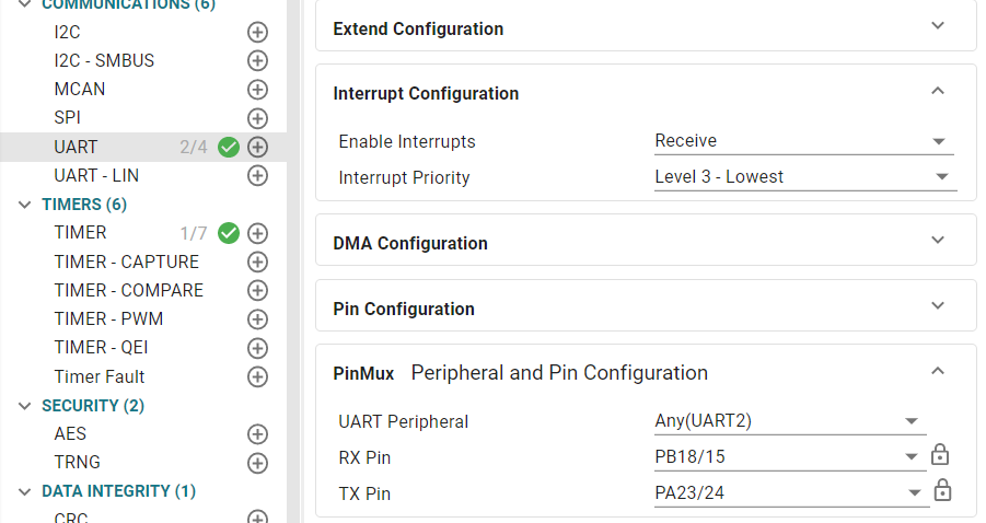
| TX | RX2 |
| RX | TX2 |
2.4 Environment Setup
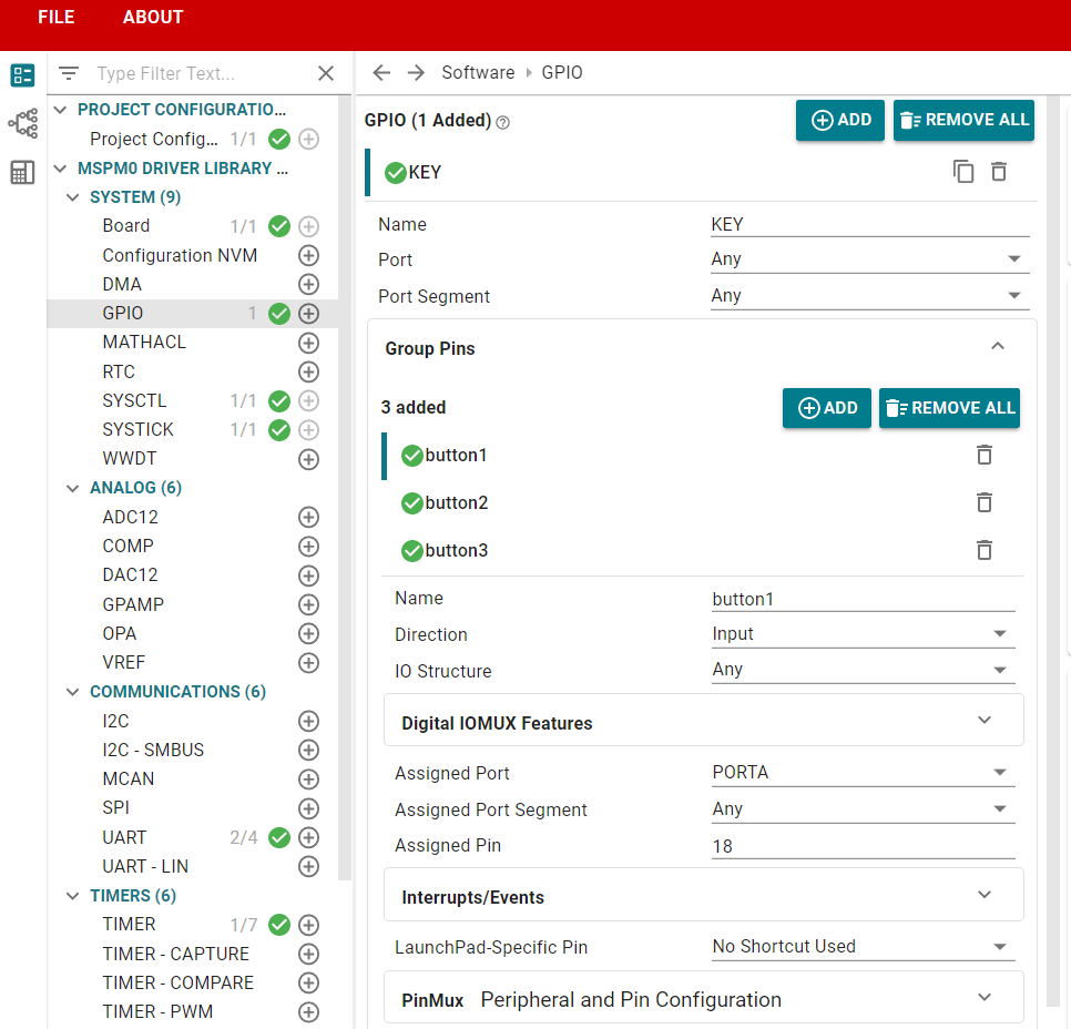
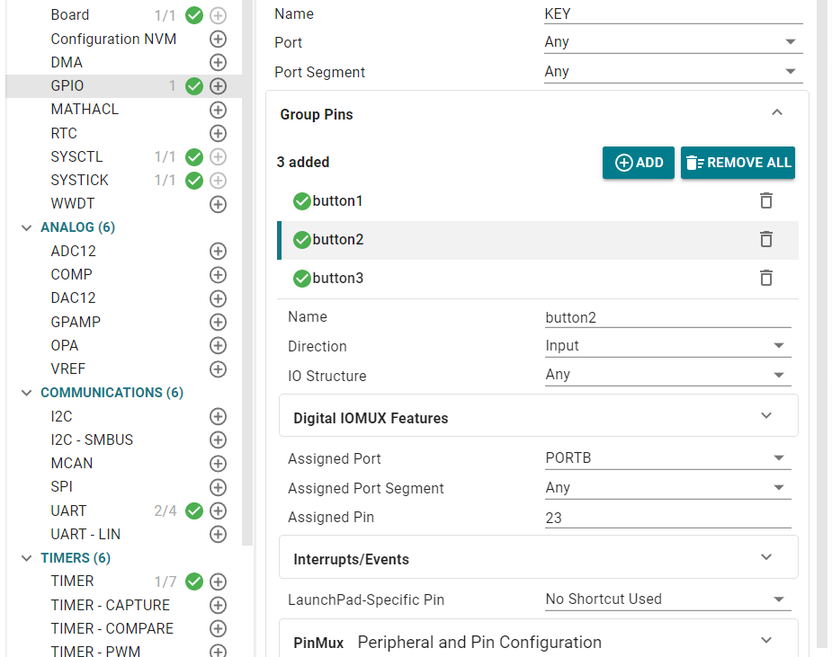
We open the sysconfig tool and add configuration as follows
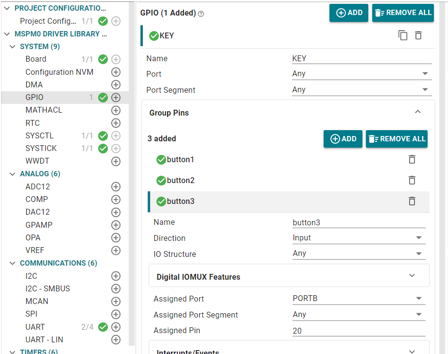
K210 serial port configuration is as follows
Enable receive interrupt
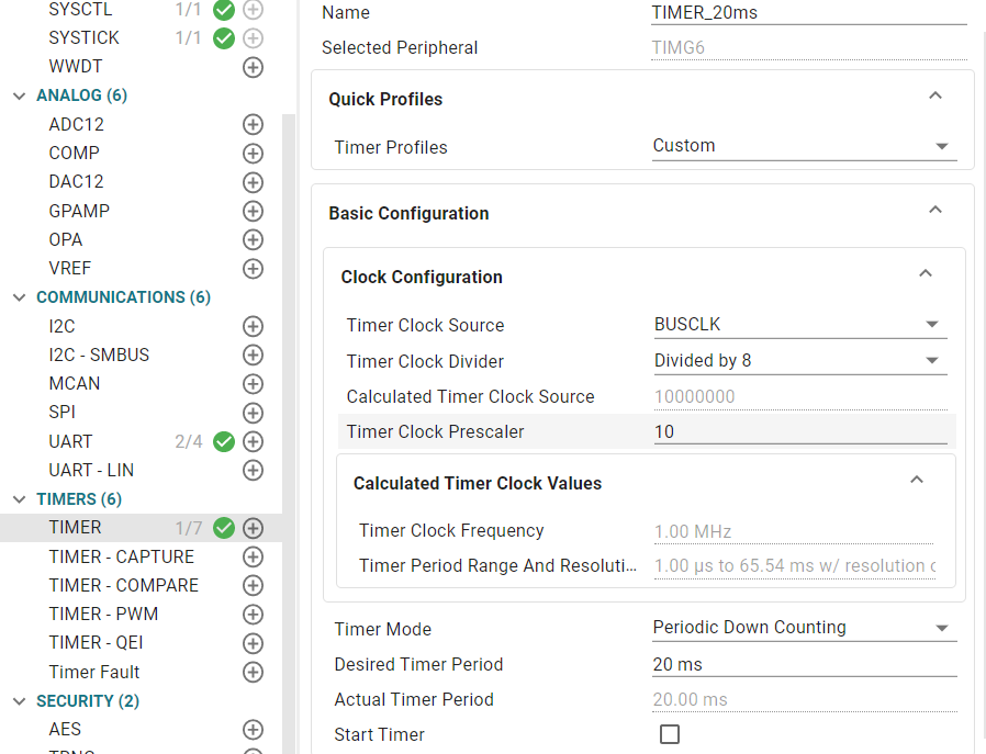
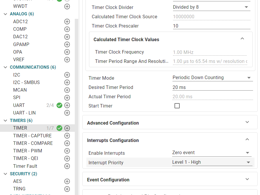
Add timer configuration for button detection
Enable zero event interrupt
2.5 Partial Code Explanation
bsp_key.c
xxxxxxxxxx// Define global button handle array, storing state information for each buttonKeyHandle_T keyHandle[KEY_NUM] = {0};uint8_t g_key_flag = 0;// Button initialization functionvoid Key_Init(void) { for (int i = 0; i < KEY_NUM; i++) { keyHandle[i].state = KEY_STATE_IDLE; keyHandle[i].press_time = 0; keyHandle[i].key_event_short = 0; keyHandle[i].key_event_long = 0; }}// Read physical state of a single buttonuint8_t Key_Read_Pin(uint8_t key_index) { // Read different pins based on button index switch (key_index) { case 0: // Read button 1 pin state, return pressed/released state based on hardware connection return (DL_GPIO_readPins(KEY_button1_PORT, KEY_button1_PIN) & KEY_button1_PIN) ? KEY_PRESSED : KEY_RELEASED ; case 1: // Read button 2 pin state return (DL_GPIO_readPins(KEY_button2_PORT, KEY_button2_PIN) & KEY_button2_PIN) ? KEY_RELEASED : KEY_PRESSED; case 2: // Read button 3 pin state return (DL_GPIO_readPins(KEY_button3_PORT, KEY_button3_PIN) & KEY_button3_PIN) ? KEY_RELEASED : KEY_PRESSED; default: return KEY_RELEASED; // Return released state by default // Return released state by default }}// Button scan handler function (needs to be called in 20ms timer interrupt)void Key_Scan_Handler(void) { for (int i = 0; i < KEY_NUM; i++) { uint8_t current_key_state = Key_Read_Pin(i); switch (keyHandle[i].state) { case KEY_STATE_IDLE: if (current_key_state == KEY_PRESSED) { // Enter debounce state keyHandle[i].state = KEY_STATE_DEBOUNCE; keyHandle[i].press_time = 0; } break; case KEY_STATE_DEBOUNCE: if (current_key_state == KEY_PRESSED) { keyHandle[i].press_time++; // Debounce time: 20ms (1 cycle), continue pressing to confirm if (keyHandle[i].press_time >= 1) { keyHandle[i].state = KEY_STATE_PRESSED; keyHandle[i].key_event_short = 1; keyHandle[i].press_time = 0; } } else { // Released during debounce, considered as jitter, return to idle state keyHandle[i].state = KEY_STATE_IDLE; } break; case KEY_STATE_PRESSED: if (current_key_state == KEY_PRESSED) { keyHandle[i].press_time++; // Long press judgment, for example 50 * 20ms = 1000ms (1 second) if (keyHandle[i].press_time >= 50) { keyHandle[i].key_event_long = 1; // Trigger long press flag } } else { // Release detected, enter release debounce state keyHandle[i].state = KEY_STATE_RELEASE; keyHandle[i].press_time = 0; } break; case KEY_STATE_RELEASE: // Release debounce state keyHandle[i].press_time++; // Release debounce, continue for 20ms (1 cycle) to consider stable release if (keyHandle[i].press_time >= 1) { keyHandle[i].state = KEY_STATE_IDLE; // Note: Short press and long press flags are cleared after main loop query, not cleared here } break; default: // Abnormal state reset to idle keyHandle[i].state = KEY_STATE_IDLE; break; } }}bsp_k210_usart.c
xxxxxxxxxx// Use button, press once to change k210's RGB colorvoid K210_Rgb_Key(void){ // If button 0 short press event is triggered if(keyHandle[0].key_event_short == 1) { // Switch sending different color commands based on send_key1 value switch (send_key1) { case 0: // Send blue command strcpy(send_buf, "$blue#"); break; case 1: // Send red command strcpy(send_buf, "$red#"); break; case 2: // Send green command strcpy(send_buf, "$green#"); break; default: send_key1 = 0; // Default value reset to 0 } send_key1 = (send_key1 + 1) % 3; uart2_send_string(send_buf); keyHandle[0].key_event_short = 0; } // If button 1 short press event is triggered if(keyHandle[1].key_event_short == 1) { // Switch sending different color commands based on send_key2 value switch (send_key2) { case 0: // Send yellow command strcpy(send_buf, "$yellow#"); break; case 1: // Send purple command (Note: correct spelling should be purple) strcpy(send_buf, "$purple#"); break; case 2: strcpy(send_buf, "$lake#"); break; default: send_key2 = 0; } send_key2 = (send_key2 + 1) % 3; uart2_send_string(send_buf); keyHandle[1].key_event_short = 0; } // If button 2 short press event is triggered if(keyHandle[2].key_event_short == 1) { // Send command to turn off RGB strcpy(send_buf, "$close#"); // Send close command through UART2 uart2_send_string(send_buf); // Clear button 2 short press event flag keyHandle[2].key_event_short = 0; }}K210 partial source code
xxxxxxxxxxwhile True: # Read data from serial port read_data = uart_A.read() # Judge whether valid data is read if read_data is not None: ... # Filter out invalid 0xFF bytes if read_data[0] != 255: # Decode byte data as UTF-8 string read_str = read_data.decode('utf-8') # Remove null characters from string (STM32 might send packets with null characters) read_str = read_str.replace('\x00', '') # Check if string matches "$xxx#" format (starts with $, ends with #) if read_str.startswith('$') and read_str.endswith('#'): # Extract valid data between $ and # (remove special symbols at start and end) recv_data = read_str.strip('$#') # Set RGB color based on received command set_RGB(recv_data)# Release serial port resources when program exits (actual运行时while True会一直循环,此处为收尾操作)uart_A.deinit() # Delete serial port object # Delete UART objectdel uart_A Program Flowchart
2.6 Main Functions
K210_Rgb_Key
| Function Prototype | void K210_Rgb_Key() |
|---|---|
| Function Description | Control the state of RGB light on k210 |
| Input Parameters | None |
| Output Parameters | None |
2.7 K210 Program Burning
Download all files in the [Program Source Code Summary] -> [Vision Application Experiment] -> [K210_SD_File] directory to the root directory of the memory card through card reader.
We can click on the tutorial link and select [Download] -> [Development Software] to access Google Drive and download the drivers and CanMV IDE .
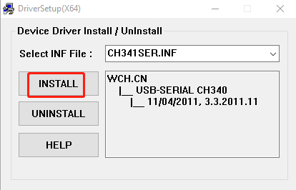
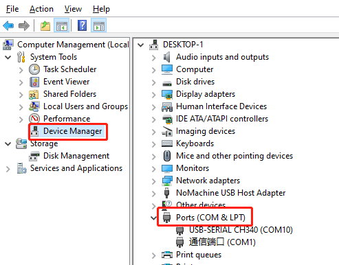
After successful installation, we connect microusb to K210 and computer. Open Device Manager and see similar device as shown below, which means our driver installation is successful. The COMX here depends on your actual situation, then we open CanMV IDE
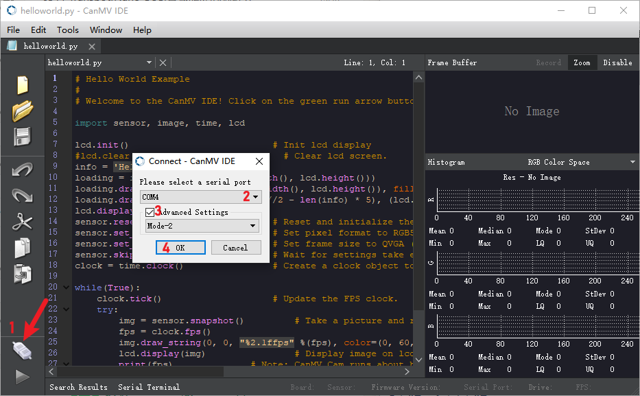
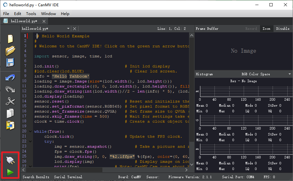
After downloading and opening CanMV IDE, we need to first drag the k210 source code provided in this course section k210_car.py to CanMV IDE to open, then connect IDE, here take helloworld.py as example
After IDE connection is successful, the phenomenon is as follows
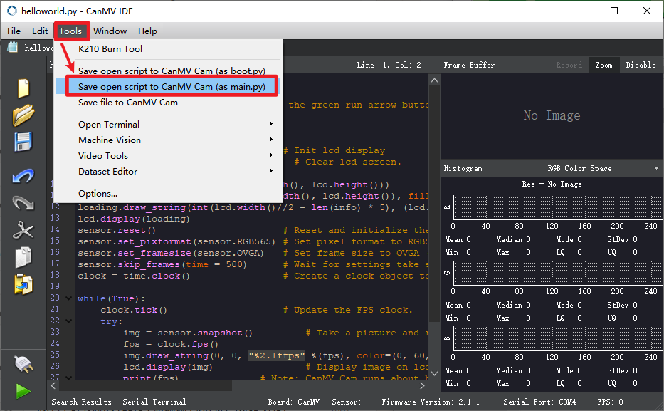
Open the top menu bar Tools -> Save currently open script as (main.py) to CanMV Cam
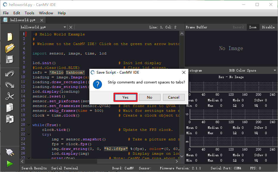
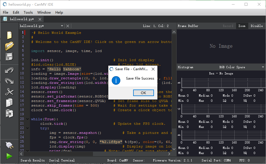
Here you can choose Yes/No. The following status indicates successful writing.
2.8 Experimental Phenomenon
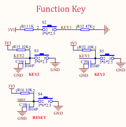
After burning the program, press KEY1, KEY2, KEY3 buttons on the development board to switch the K210 indicator status once. KEY1 pressed makes K210 light up three colors, KEY2 pressed makes K210 light up another three colors, KEY3 pressed makes K210 indicator turn off.