Welcome to MSPM0 Smart Robot Car repository
5.Infrared avoid sensor
Infrared Avoid Sensor
Infrared Avoid Sensor1. Software and Hardware2. Basic Principles2.1 Hardware Schematic2.2 Physical Connection Diagram2.3 Control Principle3. Project Configuration3.1 Description3.2 Pin Configuration4. Main Functions4.1 User Functions5. Experimental Phenomenon
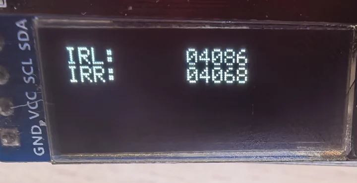
This tutorial demonstrates: displaying the distance of infrared sensors through OLED.
1. Software and Hardware
KEIL
MSPM0G3507 Development Board
Type-C data cable or DAP-Link
For programming download or simulation to the development board
2. Basic Principles
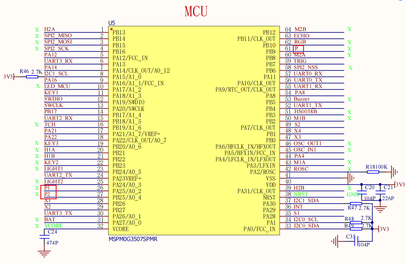
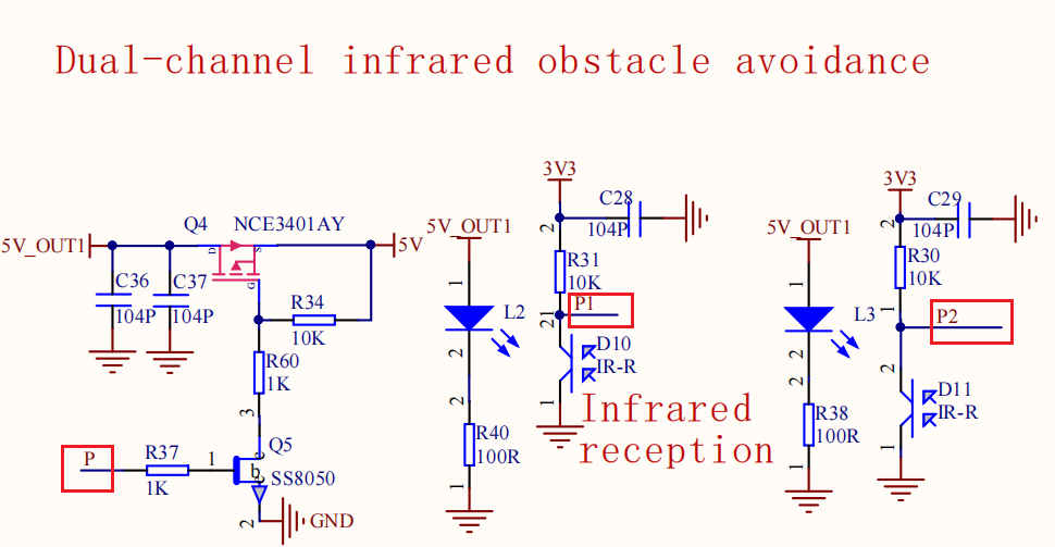
2.1 Hardware Schematic
2.2 Physical Connection Diagram
.png)
2.3 Control Principle
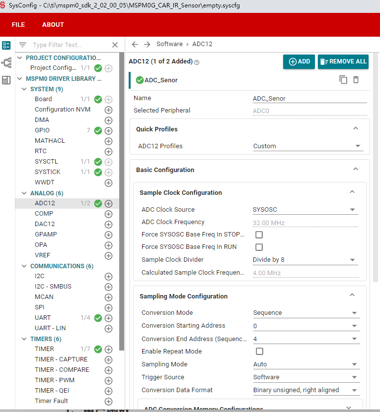
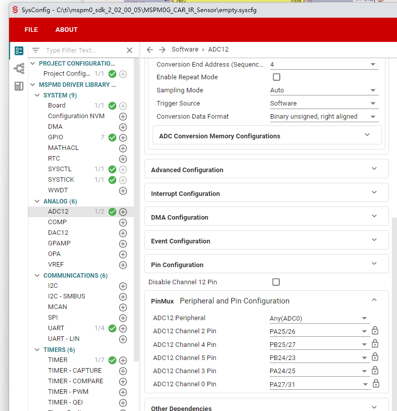
Through two-channel ADC conversion, the analog voltage output by the infrared obstacle avoidance module can be converted into digital values; the value range is 0 to 2^12-1 (i.e., 0 to 4095).
| Infrared Avoidance (Development Board Integrated) | Corresponding Pin |
|---|---|
| P1 | PA25 (controls left obstacle avoidance module switch) |
| P2 | PB25 (controls right obstacle avoidance module switch) |
| P | PB9 (AD collection) |
3. Project Configuration
3.1 Description
You can refer to the basic tutorial to complete the development environment setup.
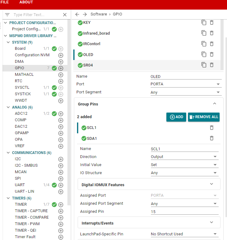
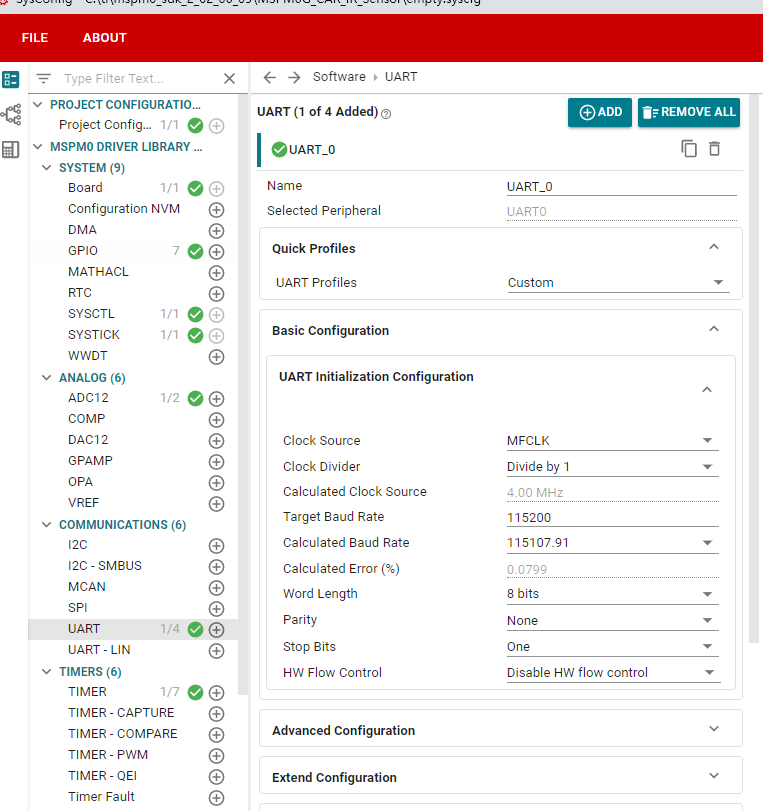
3.2 Pin Configuration

4. Main Functions
Mainly introduces the functional code written by users. For detailed code, you can open the project files we provide and view the source code in the Bsp folder.
4.1 User Functions
Function: void Open_IR_Switch(void)
| Function Prototype | void Open_IR_Switch(void) |
|---|---|
| Function Description | Open infrared obstacle avoidance output |
| Input Parameters | None |
| Output Parameters | None |
Function: void Close_IR_Switch(void)
| Function Prototype | void Close_IR_Switch(void) |
|---|---|
| Function Description | Close infrared obstacle avoidance output |
| Input Parameters | None |
| Output Parameters | None |
5. Experimental Phenomenon
Phenomenon:
OLED displays the values after ADC conversion of two-channel infrared sensors.