Welcome to MSPM0 Smart Robot Car repository
10.K230 Scenario-based autonomous driving
k230 Scenario-Based Autonomous Driving
k230 Scenario-Based Autonomous DrivingSerial CommunicationHardware ConnectionPartial Code AnalysisExperimental Phenomena
This case requires the use of an eight-channel intelligent line-following module (infrared line-following module)
Serial Communication
USART: Universal Synchronous Asynchronous Receiver/Transmitter. It can automatically generate data frame timing based on a byte of data in the data register and send it out from the TX pin. It can also automatically receive data frame timing from the RX pin, concatenate them into a byte of data, and store it in the data register. This experiment uses UART2.
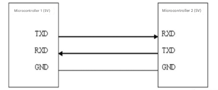
When using serial communication, both communicating parties must be "on the same channel." "On the same channel" refers to using the same communication protocol. USART (Ultra-Mobile Serial Port) Conventions: During communication, data must be transmitted in "frames." A single frame of data in a USART port includes: Start Bit + Data Bits + Parity Bit + Stop Bit. Where: 1) Start Bit: Fixed as a low-level signal for one cycle. 2) Data Bits: Can be agreed upon by both communicating parties, ranging from 5 to 9 bits. 3) Parity Bit: The USART port uses parity checking, which can be agreed upon by both communicating parties. 4) Stop Bit: Optional high-level signal for 0.5 to 2 cycles. Simultaneously, to synchronize the transmission and reception speeds of both parties, the number of data frames transmitted per second needs to be agreed upon, called the baud rate. Typical baud rates include 9600, 115200, 57600, etc.
Hardware Connection
connected relation
(Note: The wiring in the following picture is for reference only. We come with a K230 dual-ended PH2.0 4-pin all-black cable at the factory, which has a fool-proof design. You don't need to worry about wiring issues.)

Wiring relationship table
| 8-channel infrared tracking sensor module | MSPM0G3507 |
|---|---|
| 5V | 5V |
| GND | GND |
| RX | TX0 |
| TX | RX0 |
| k230 vision module | MSPM0G3507 |
|---|---|
| 5V | 5V |
| GND | GND |
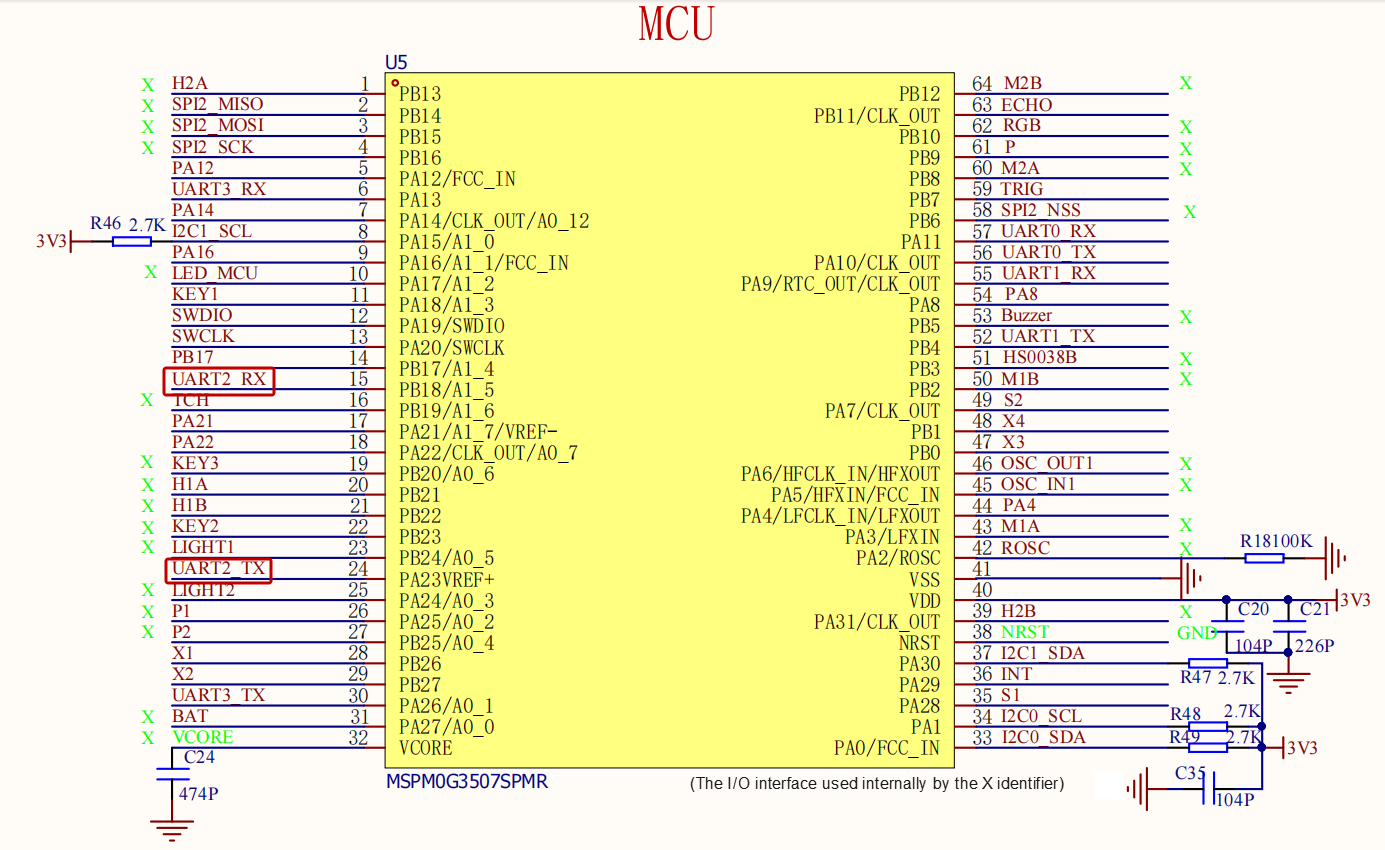
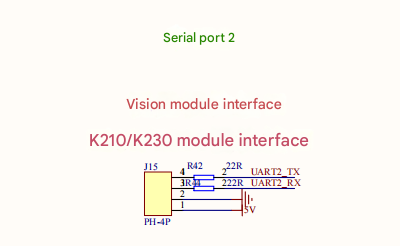
| RX | TX2 |
| TX | RX2 |
Schematic diagram section
k230 Protocol
After the k230 identifies a road sign, it sends a data frame via serial port in the format "$09" + "signature content ID," + "#". For example: "$091, #".
When the microcontroller receives this data frame, it checks each bit. If the content is "$09", it continues receiving. When it receives "#", it indicates that a data packet has been completed. The microcontroller parses the information transmitted by the k230 and compares the signature content ID with a specific command. If it matches the command, the vehicle will perform the corresponding operation.
Control Flowchart
Partial Code Analysis
bsp_k230.c
xvoid data_deal_k230(uint8_t data) { // Process data sent by k230 device, parse single-byte data according to specific format switch(data_step) { case 0: // Reset all states to ensure a clean start len = 0; memset(k230_data, 0, k230_DATA_MAX_LEN); if(data == '$') { // Detected start character '$', move to next state data_step++; } break; case 1: if(data == '0') { // Matched second feature character '0', move to next state data_step++; } else { // Reset state if not matched data_step = 0; } break; case 2: if(data == '9') { // Matched third feature character '9', move to next state data_step++; } else { // Reset state if not matched data_step = 0; } break; case 3: // Receiving x value (numeric digits) if(data == ',') { // End of x reception, enter end character verification phase if(len == 0 || len > k230_DATA_MAX_LEN) { // x is empty or exceeds max length, invalid data data_step = 0; } else { // Valid data length, enter end character waiting state data_step++; // Move to state 4 waiting for '#' } } else if(data >= '0' && data <= '9') { // Only receive numeric digits if(len < k230_DATA_MAX_LEN) { // Limit max length to prevent overflow k230_data[len++] = data; } else { // Exceeds max length, treat as invalid data data_step = 0; len = 0; memset(k230_data, 0, k230_DATA_MAX_LEN); } } else { // Received non-numeric and non-',' character, invalid data data_step = 0; len = 0; memset(k230_data, 0, k230_DATA_MAX_LEN); } break; case 4: // Verify end character '#' if(data == '#') { // Complete format match deal_msg(len); // Process received valid message } // Reset state regardless of whether '#' is received (to avoid residue) data_step = 0; len = 0; memset(k230_data, 0, k230_DATA_MAX_LEN); break; }}
void deal_msg(uint8_t length) { // Process parsed message, convert digits and verify range data_id = 0; if(length == 1) { // Single-byte digit conversion data_id = k230_data[0] - '0'; } else if(length == 2) { // Two-byte digit conversion (tens place + units place) uint8_t data_H = k230_data[0] - '0'; uint8_t data_L = k230_data[1] - '0'; data_id = data_H * 10 + data_L; } // Verify if data_id is within 1-11 range if(data_id >= 1 && data_id <= MAX_ID) { stop_flag = 0; // Valid data, normal processing } else { stop_flag = 1; // Invalid data, set stop flag }}main.py
xxxxxxxxxx# If targets are detected (det_boxes is not an empty list)if det_boxes:    # Iterate over each detected target    for det_boxe in det_boxes:        # det_boxe is a list or tuple containing information like (label_id, confidence, x1, y1, x2, y2)        x1, y1, x2, y2 = det_boxe[2], det_boxe[3], det_boxe[4], det_boxe[5]                # Calculate the width and height of the bounding box to be displayed on the screen        # based on the ratio between the screen resolution and the AI model's output resolution.        # DISPLAY_WIDTH, DISPLAY_HEIGHT: The actual resolution of the screen.        # OUT_RGB888P_WIDTH, OUT_RGB888P_HEIGHT: The resolution of the AI model's output.        w = float(x2 - x1) * DISPLAY_WIDTH // OUT_RGB888P_WIDTH        h = float(y2 - y1) * DISPLAY_HEIGHT // OUT_RGB888P_HEIGHT
        # Draw a rectangle on the OSD (On-Screen Display) layer.        # color_four[det_boxe[0]][1:] selects the corresponding color based on the target's label ID.        osd_img.draw_rectangle(            int(x1 * DISPLAY_WIDTH // OUT_RGB888P_WIDTH),              int(y1 * DISPLAY_HEIGHT // OUT_RGB888P_HEIGHT),             int(w),              int(h),             color=color_four[det_boxe[0]][1:]  # Get color based on label ID        )                # Get the label name corresponding to the label ID        label = labels[det_boxe[0]]                # Round the confidence score to two decimal places and convert it to a string        score_str = str(round(det_boxe[1], 2))        score = round(det_boxe[1], 2)
        # If the confidence score is greater than 0.7        if score > 0.7:            # Draw the label name and confidence score above the bounding box            osd_img.draw_string_advanced(                int(x1 * DISPLAY_WIDTH // OUT_RGB888P_WIDTH),                 int(y1 * DISPLAY_HEIGHT // OUT_RGB888P_HEIGHT) - 50, # Position above the box                32,  # Font size                label + " " + score_str,  # Text to display                color=color_four[det_boxe[0]][1:] # Color for the text            )
            # Construct the data string to be sent via UART            # For example, if a target with label ID 0 is detected, the string sent is "$090,#"            send_data = "$" + "09" + str(det_boxe[0]) + ',' + "#"                        # Send the data through the UART serial port            uart.send(send_data)                        # Print the sent data to the console for debugging purposes            print(send_data)
    # Display the OSD image layer. The parameters (0, 0) specify the top-left corner position.    # Display.LAYER_OSD3 indicates that this is drawn on the third OSD layer.    Display.show_image(osd_img, 0, 0, Display.LAYER_OSD3)        # Manually perform garbage collection to free up memory.    # This is useful in memory-constrained environments to prevent memory leaks.    gc.collect()
Main Functions
data_deal_k230
| Function Prototype | void data_deal_k230(uint8_t data) |
|---|---|
| Function Description | Processes data sent from k230, parsing it according to a fixed format (starting with '$', identified by "09", data is numbers, separated by ',', ending with '#'). Valid data is processed through deal_msg; invalid data has its state reset. |
| Input Parameter | data: Single-byte data received from k230 |
| Return Value | None |
deal_msg
| Function Prototype | void deal_msg(uint8_t length) |
|---|---|
| Function Description | Converts the parsed numeric data (length 1 or 2) into an ID value, checks if the ID is within the range of 1-11, and sets stop_flag if valid. Set to 0 otherwise, set to 1. |
| Input Parameter | length: Length of the parsed numeric data. |
| Return Value | None. |
set_dataid
| Function Prototype | void set_dataid(k230_TYPE id) |
|---|---|
| Function Description | Sets the value of data_id (used for clearing, etc.). |
| Input Parameter | id: The ID value to be set. |
| Return Value | None. |
get_dataid
| Function Prototype | uint8_t get_dataid(void) |
|---|---|
| Function Description | Gets the current data_id value. |
| Input Parameter | None. |
| Return Value | uint8_t type, the current data_id. |
Reverse_parking_no2
| Function Prototype | void Reverse_parking_no2(void) |
|---|---|
| Function Description | Control the car to reverse into parking space No. 2: stop after reversing for a specified time, stop after turning left for a specified time, then reverse for another specified time. |
| Input Parameters | None |
| Return Value | None |
Reverse_parking_no1
| Function Prototype | void Reverse_parking_no1(void) |
|---|---|
| Function Description | Control the car to reverse into parking space No. 1: stop after reversing for a specified time, stop after turning right for a specified time, then reverse for another specified time and stop. |
| Input Parameters | None |
| Return Value | None |
Road_sign_right
| Function Prototype | void Road_sign_right(void) |
|---|---|
| Function Description | Right turn control based on road sign: adjusts the speed of the left and right motors according to sensor status to achieve a right turn or correct direction. |
| Input Parameters | None |
| Return Value | None |
Road_sign_left
| Function Prototype | void Road_sign_left(void) |
|---|---|
| Function Description | Road sign left turn control (left turn priority lane following): Adjusts the speed of the left and right motors according to the sensor status to achieve left turn or direction correction. |
| Input Parameters | None |
| Return Value | None |
Road_sign_speedlimit
| Function Prototype | void Road_sign_speedlimit(void) |
|---|---|
| Function Description | Low-speed lane following control: Based on the speed limit, fine-tunes the speed of the left and right motors according to the sensor status to achieve turning or straight-line movement. |
| Input Parameters | None |
| Return Value | None |
LineWalking_PWM
| Function Prototype | void LineWalking_PWM(void) |
|---|---|
| Function Description | PWM-based Line-following Control: Acquires infrared sensor status and adjusts the PWM values of the left and right motors based on different detection conditions to achieve straight-line or turning control. |
| Input Parameters | None |
| Return Value | None |
LineCheck
| Function Prototype | int LineCheck(void) |
|---|---|
| Function Description | Detects whether the car is currently on a black or white line: Returns WHITE if no black line is detected by any sensor, otherwise returns BLACK. |
| Input Parameters | None |
| Return Value | int type, WHITE (white line) or BLACK (black line) |
Experimental Phenomena
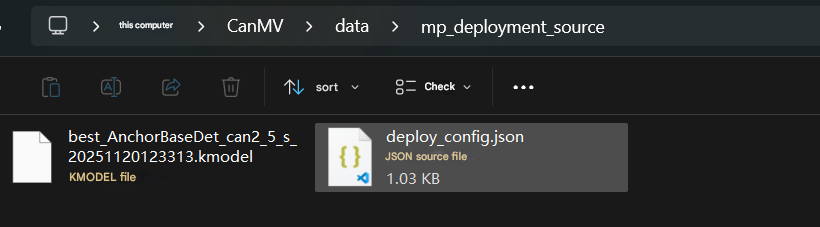
Before starting this experiment, first copy the mp_deployment_source folder from the K230 source code folder to the CanMV/data directory (path shown below). Then, burn main.py to the K230.
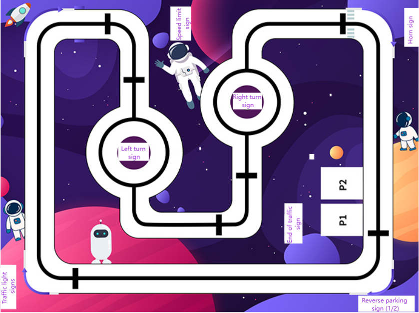
The road markers placed on the map in this tutorial are shown in the image below. After successfully downloading the program, place the car on the map, turn it on, and wait a while until the K230 screen lights up. The car will then begin following the line. Due to factors such as motor mechanical errors, ground material, and battery power, line following and reversing scenarios need to be adjusted according to the actual scenario.
Upon detecting a speed limit sign, the car will follow the line at a speed not exceeding the speed limit sign.
Upon detecting an end-of-speed-limit sign, the vehicle resumes normal lane-following movement.
Upon detecting a left/right turn, the vehicle prioritizes the left/right turn.
Upon detecting a horn, the vehicle stops, sounds the horn twice, and then resumes normal lane-following movement.
Upon recognizing traffic lights, the vehicle stops at red lights and proceeds at green lights.
Regarding parking spaces 1 and 2, if the vehicle recognizes space 1, it will enter space 1; if it recognizes space 2, it will reverse into space 2.