yahboom
HomeLearn
Solution
Blog
Online Store
About Us
EN/中文
RDK X3 Robot📖
01. About RDK-X3-Robot
1. Instructions
  • 1. Introduction
  • 2. FAQ
  • 3. Battery and charger use precautions
  • 4.TF card expand capacity
2. Common problem analysis
02. Assembly video
  • Part1-Install Motor
  • Part2-Install Battert Fixing Column
  • Part3-Install Motor Coupling
  • Part4-Install Mecanum wheel
  • Part5-Install Expansion Board
  • Part6-Wiring Show
  • Part7-Install Main Control Board
  • Part8-Install Car Top Plate and Antenna
  • Part9-Install OLED Screen
  • Part10-Install Depth Camera(Optional)
  • Part11-Install OLED Screen
  • Part12-Install HD Camera
  • Part13-Install Top Plate
  • Part14-Install Right Side Plate
  • Part15-Motor Wiring Show
  • Part16-lnstall Car Body
  • Part17-Install Battery
  • Part18-Install Lidar
03. Remote control tutorial
  • 1. The phone APP remote tutorial
  • 2. USB wireless controller remote tutorial
04. ROS functional tutorial
  • 1. Introduction of extension board
  • 2. Set up STM32 development environment
  • 3. Key control buzzer sound
  • 4. FreeRTOS application
  • 5. Serial communication
  • 6. SBUS model remote control
  • 7. CAN bus communication
  • 8. RGB color light strip
  • 9. Timer interrupt control PWM servo
  • 10. Control serial steering gear
  • 11. Nine-axis attitude sensor to obtain data
  • 12. Control motor forward and reverse
  • 13. The timer captures encoder data
  • 14. Theory of robot kinematics analysis
  • 15. PID control robot motion
05. Basic control tutorial
  • 1. Update the firmware of the expansion module
  • 2. Install the Python driver library
  • 3. Set the type of bottom car
  • 4. Open and close the APP program control
  • 5. Turn hotspot mode on and off
  • 6. The buzzer blows
  • 7. Control the motor forward and reverse
  • 8. Control robot movement
  • 9. OLED display
  • 10. Control fan and lamp effect
06. Development environment setup
  • 1. Virtual Machine
  • 2. Linux Basics
  • 3. Remote connection
  • 4. Multi-computer communication configuration
  • 5. Bind the device ID
  • 6. Image installation and backup
07. ROS2 Basic Course
  • 1. Introduction to ROS2
  • 2. ROS2 install Humble
  • 3. ROS2 development environment
  • 4. ROS2 workspace
  • 5. ROS2 function package
  • 6. ROS2 node
  • 7. ROS2 topic communication
  • 8. ROS2 service communication
  • 9. ROS2 action communication
  • 10. ROS2 custom interface message
  • 11. ROS2 parameter service case
  • 12. ROS2 meta-function package
  • 13. ROS2 distributed communication
  • 14. ROS2 DDS
  • 15. ROS2 time related API
  • 16. ROS2 common command tools
  • 17. ROS2 rviz2 use
  • 18. ROS2 rqt toolbox
  • 19. ROS2 Launch startup file configuration
  • 20. ROS2 recording and playback tool
  • 21. ROS2 URDF model
  • 22. ROS2 Gazebo simulation platform
  • 23. ROS2 TF2 coordinate transformation
08. Robot chassis control
  • 1. PID algorithm theory
  • 2. Robot information release
  • 3. Robot control
  • 4. Robot state estimation
  • 5. Robot calibration
  • 6. Robot trajectory tracking
  • 7. URDF model
09. Lidar courses
  • 1. Introduction and use of lidar
  • 2. Lidar obstacle avoidance
  • 3. Lidar following
  • 4. Lidar guard
  • 5. Patrol
  • 6. gmapping algorithm
  • 7. cartographer algorithm
  • 8. Navigation and obstacle avoidance
  • 9. App mapping and navigation
10. OpenCV courses
  • 1. Introduction to OpenCV
  • 2. OpenCV geometric transformation
  • 3. OpenCV image processing
  • 4. OpenCV image beautification
  • 5. Qr code creation and identification
11. MIPI camera course
  • 1. Camera driver
  • 2. Adjust the color HSV value
  • 3. Color recognition
  • 4. Color tracking
  • 5. Color follow
  • 6. Qr code command
  • 7. Face detection
  • 8. Object detection
  • 9. Visual Inspection -OpenCV
  • 10. Visual inspection - Deep learning
  • 11. Human tracking
  • 12. Gesture control
12. Depth Camera courses
  • 1. Use depth camera
  • 2. Calibration of camera internal reference
  • 3. ROS+OpenCV Foundation
  • 4. AR vision
  • 5. Color tracking
  • 6. Object tracking
13. Multi vehicle control
  • 1. Multi-vehicle synchronous control
  • 2. Multi-vehicle navigation
Remote login control
  • 1. VNC and SSH remote login
  • 2. Jupyter lab login and case code running
Download
  • RemoteCtrl_APP(iOS/Android))
  • Mapping_APP(iOS_Android)
  • Code
  • System File
  • VM_File
  • Manual
  • Software_File
  • Hardware_File
  • ROS2_Basic_VM
Download ZIP

Welcome to RDK X3 Robot repository

1. Introduction of extension board

1.Introduction to expansion board

1.Introduction to expansion boardStatement:1.1. Distribution diagram of components on the front of the expansion board1.2. Distribution diagram of components on the back of the expansion board

Statement:

ROS driver board function tutorial is mainly based on ROS expansion board resources, some components (such as PWM servo, serial port servo, etc.) are not included in RDK-X3-Robot robot car.


1.1. Distribution diagram of components on the front of the expansion board
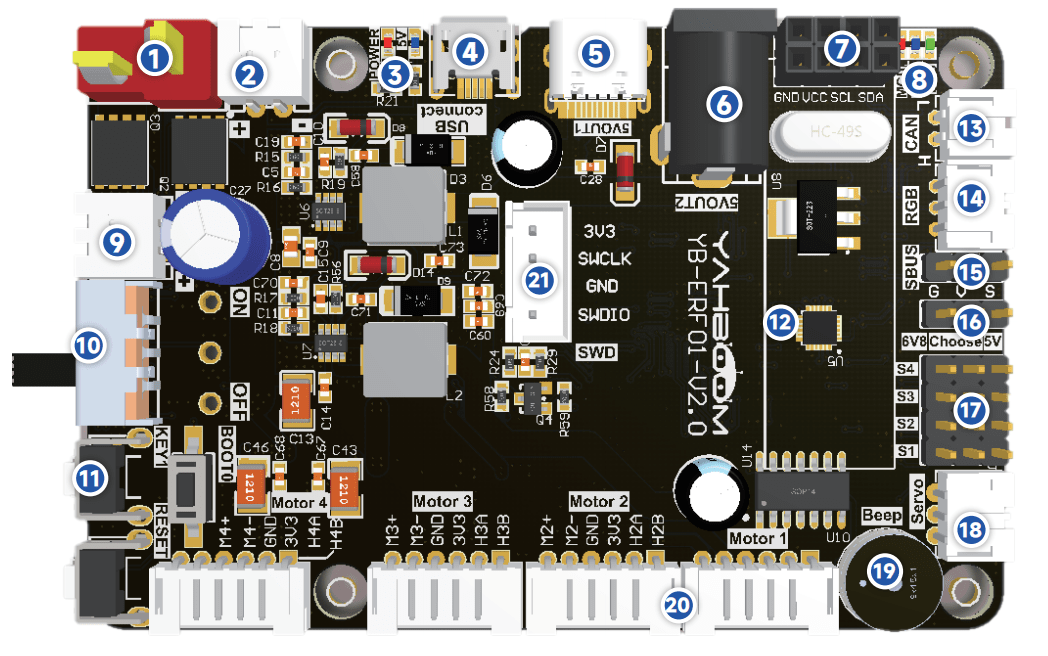
image-20230601102442563

① T-type DC 8V power input port: serves as the main power input of the expansion board and connects to the DC 8V power supply or 8V battery.

②⑨DC 8V power output: Supply DC 8V power to the outside.

③ Power indicator: indicates whether the power supply is normal.

④micro USB data interface: connect the host communication and burning program.

⑤type-C interface: provides DC 5V to the outside, only power supply can not communicate.

⑥DC 5V output interface: can supply power to Jetson Nano.

⑦I2C interface: It can be connected to external I2C devices, such as OLED screens.

⑧ Indicator: data indicator and 6.8V voltage indicator.

⑩DC 8V power switch: main power switch.

⑪ Key: Key KEY1: A user function key that enables customization through programming. Button RESET: on-board MCU reset button. Key BOOT0: The on-board microcontroller BOOT0 key is used for microcontroller to enter the burning mode.

⑫ Nine-axis attitude sensor: provides the current attitude of the expansion board. ⑬ CAN interface: connection CAN equipment. ⑭ RGB color lamp interface: connect the RGB color lights. ⑮ The SBUS interface: Connects to the receiver of the model airplane remote control.

⑯ PWM servo voltage switch: change the position of the jumper cap can choose 6.8 V or 5 V voltage of PWM servo power supply. ⑰ PWM servo interface: can be connected to 6.8 V or 5 V voltage PWM servo, need to choose the corresponding voltage according to the servo voltage in ⑯. ⑱ serial interface: the steering gear is connected to a serial port servo manipulator. ⑲ Buzzer: used to sound alarms.

⑳ four-way motor connection port: Connect four motors. Please refer to the corresponding course documents according to the connection method of different models.

㉑SWD debugging port: Connects to the SW port on the ST-Link or J-Link, and is used to debug the MCU or download the firmware of the MCU.

1.2. Distribution diagram of components on the back of the expansion board
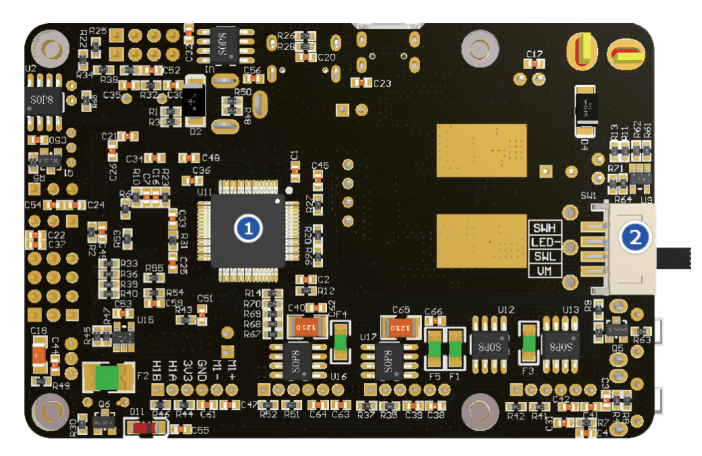
image-20230601102959333

① On-board microcontroller: mainly responsible for the control of peripherals on the expansion board, such as buzzer, motor drive, etc. ② Metal button switch PH2.0 interface: external metal switch can be connected in parallel with the on-board power switch, only need to open one of the switches, you can turn on the power.


USB wireless controller remote tutorial
Set up STM32 development environment

COMPANY

  • About us
  • Team Style
  • Blog

LEARNING & EXPLORATION

  • Tutorials
  • Edge AI hardware
  • Educational robots
  • Embedded intelligent hardware

WHERE TO BUY

  • Yahboom Online Store
  • Amazon
  • Alibaba
  • AliExpress
  • Mercado

TECHNOLOGY SUPPORT

  • Email: support@yahboom.com

BE A DISTRIBUTOR

  • Email: sales@yahboom.com
QR Code

Copyright © 2017-2026 Yahboom. All Rights Reserved.

EN/中文