Welcome to RDK X3 Robot repository
5. Robot calibration
5. Robot calibration
5. Robot calibration5.1. Description of program functions5.2. Program Code Reference Path5.3. Program Startup5.4. Core Source Code Parsing
5.1. Description of program functions
After the program is run, the dynamic parameter adjuster is used here to adjust the parameters to calibrate the linear and angular speed of the car. The intuitive embodiment of the calibration line speed makes the car go straight forward 1 meter, to see how far it actually runs and whether it is within the error range; The visual representation of calibration angular velocity allows the car to rotate 360 degrees to see if the Angle of rotation of the car is within the error range.
5.2. Program Code Reference Path
After SSH connection car, the location of the function source code is located at,
xxxxxxxxxx#标定线速度源码# Calibration line speed source code/userdata/yahboomcar_ws/src/yahboomcar_bringup/yahboomcar_bringup/calibrate_linear.py#标定角速度源码# Calibration angular velocity source code/userdata/yahboomcar_ws/src/yahboomcar_bringup/yahboomcar_bringup/calibrate_angular.py5.3. Program Startup
After SSH connects to the car, terminal input,
xxxxxxxxxx#启动底盘# Start chassisros2 launch yahboomcar_bringup yahboomcar_bringup_launch.py#标定线速度# Calibrate the line speedros2 run yahboomcar_bringup calibrate_linear#标定角速度# Calibrate the angular velocityros2 run yahboomcar_bringup calibrate_angularOpen the virtual machine terminal, input,
xxxxxxxxxx#动态参数调节# Dynamic parameter adjustmentros2 run rqt_reconfigure rqt_reconfigure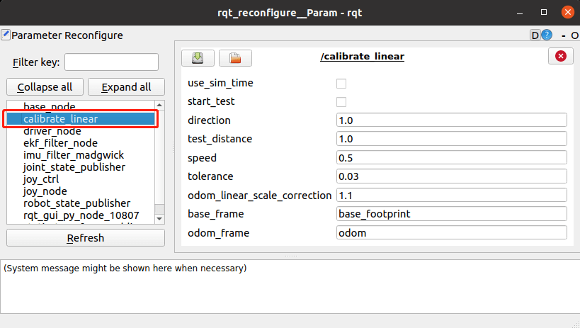
Take the calibration line speed as an example, click [start_test] car calibration x direction line speed, observe whether the car moved the test_distance distance, the default setting here is 1m, before calibration can customize the test distance, must be a decimal, set the click in the blank, the program will automatically write. If the car moves farther than the acceptable error range (the value of the tolerance variable), then the value of odom_linear_scale_correction is set. Here's what each parameter means,
| Parameters | Meanings |
|---|---|
| rate | release frequency(can need not modify) |
| test_distance | The distance from which the line speed is tested |
| speed | The magnitude of the line speed |
| tolerance | The acceptable error |
| odom_linear_scale_correction | The ratio factor |
| start_test | To start the test |
| direction | direction (linear velocity test X (1) Y direction (0)) |
| base_frame | listens for the parent coordinate of the TF transform |
| odom_frame | listens for the sub-coordinate of the TF transformation |
The variable Settings for testing angular velocity are roughly the same, but test_distance becomes test_angle and speed becomes angular velocity.
5.4. Core Source Code Parsing
This program mainly uses TF to monitor the transformation between coordinates to achieve, by monitoring the coordinate transformation between base_footprint and odom to let the robot know "how far I go now/how many degrees I turn now".
Take calibrate_linear.py as an example. The core code is as follows:
xxxxxxxxxx#监听TF变换# Monitor TF transformationdef get_position(self): try: now = rclpy.time.Time() trans = self.tf_buffer.lookup_transform(self.odom_frame,self.base_frame,now) return trans except (LookupException, ConnectivityException, ExtrapolationException): self.get_logger().info('transform not ready') raise return#获取当前的xy坐标,根据之前的xy坐标,计算距离# Get the current xy coordinates and calculate the distance based on the previous xy coordinatesself.position.x = self.get_position().transform.translation.xself.position.y = self.get_position().transform.translation.yprint("self.position.x: ",self.position.x)print("self.position.y: ",self.position.y)distance = sqrt(pow((self.position.x - self.x_start), 2) + pow((self.position.y - self.y_start), 2))distance *= self.odom_linear_scale_correctioncalibrate_angular.py core code is as follows:
xxxxxxxxxx#这里同样是监听了TF变换,获取到了当前位姿信息,只不过这里还做了转换,把四元数转了欧拉角的转换,然后再返回# Here is also listening to the TF transformation to obtain the current pose information, but here is also a conversion, the quaternion to the Euler Angle conversion, and then returndef get_odom_angle(self): try: now = rclpy.time.Time() rot = self.tf_buffer.lookup_transform(self.odom_frame,self.base_frame,now) print("orig_rot: ",rot.transform.rotation) cacl_rot = PyKDL.Rotation.Quaternion(rot.transform.rotation.x, rot.transform.rotation.y, rot.transform.rotation.z, rot.transform.rotation.w) #print("cacl_rot: ",cacl_rot) angle_rot = cacl_rot.GetRPY()[2] #print("angle_rot: ",angle_rot) return angle_rot except (LookupException, ConnectivityException, ExtrapolationException): self.get_logger().info('transform not ready') raise return#计算旋转角度# Calculate the rotation Angleself.odom_angle = self.get_odom_angle()self.delta_angle = self.odom_angular_scale_correction * self.normalize_angle(self.odom_angle - self.first_angle)The published TF transform is published in the base_node node, the code path is,
xxxxxxxxxx/userdata/yahboomcar_ws/src/yahboomcar_base_node/src/base_node.cppThis node will receive /vel_raw data, release odom data through mathematical calculation, and release TF transformation. The core code is as follows:
xxxxxxxxxx#计算xy坐标以及xyzw四元数的值,xy两点坐标表示位置,xyzw四元数表示姿态# Calculate the xy coordinates and the value of the xyzw quaternion, where the xy two-point coordinates represent the position and the xyzw quaternion represents the attitudedouble delta_heading = angular_velocity_z_ * vel_dt_; //radiansdouble delta_x = (linear_velocity_x_ * cos(heading_)-linear_velocity_y_*sin(heading_)) * vel_dt_; //mdouble delta_y = (linear_velocity_x_ * sin(heading_)+linear_velocity_y_*cos(heading_)) * vel_dt_; //m x_pos_ += delta_x;y_pos_ += delta_y;heading_ += delta_heading;tf2::Quaternion myQuaternion;geometry_msgs::msg::Quaternion odom_quat ; myQuaternion.setRPY(0.00,0.00,heading_ );#发布TF变换# Release TF transformgeometry_msgs::msg::TransformStamped t;rclcpp::Time now = this->get_clock()->now();t.header.stamp = now;t.header.frame_id = "odom";t.child_frame_id = "base_footprint";t.transform.translation.x = x_pos_;t.transform.translation.y = y_pos_;t.transform.translation.z = 0.0;t.transform.rotation.x = myQuaternion.x();t.transform.rotation.y = myQuaternion.y();t.transform.rotation.z = myQuaternion.z();t.transform.rotation.w = myQuaternion.w();tf_broadcaster_->sendTransform(t);