Welcome to RDK X3 Robot repository
7. URDF model
7. URDF model
7. URDF model7.1 Program function description7.2 Program code reference path7.3. Program Startup7.4 Introduction to URDF7.4.1. link7.4.2. joints
7.1 Program function description
After running the relevant program on the virtual machine side, the URDF model file of the car can be displayed in rviz. The car end also contains relevant programs, but because there is no visual interface, rviz will not be started when running, but the tf transformation of chassis and sensor coordinate systems will still be released for subsequent functions.
7.2 Program code reference path
Virtual machine The location of the function source code is located in,
xxxxxxxxxx/home/yahboom/dev_ws/src/yahboomcar_rviz/launch/yahboomcar_urdf_launch.pyWhere, the path of URDF model file is,
xxxxxxxxxx/home/yahboom/dev_ws/src/yahboomcar_rviz/urdf/yahboomcar.urdf
After SSH connection to car , the location of the relevant source code is located,
xxxxxxxxxx/userdata/yahboomcar_ws/src/yahboomcar_description/launch/description_launch.pyThe path of the URDF model file is,,
xxxxxxxxxx/userdata/yahboomcar_ws/src/yahboomcar_description/urdf/yahboomcar.urdf
7.3. Program Startup
In the VM terminal, enter,
xxxxxxxxxxros2 launch yahboomcar_description display_launch.py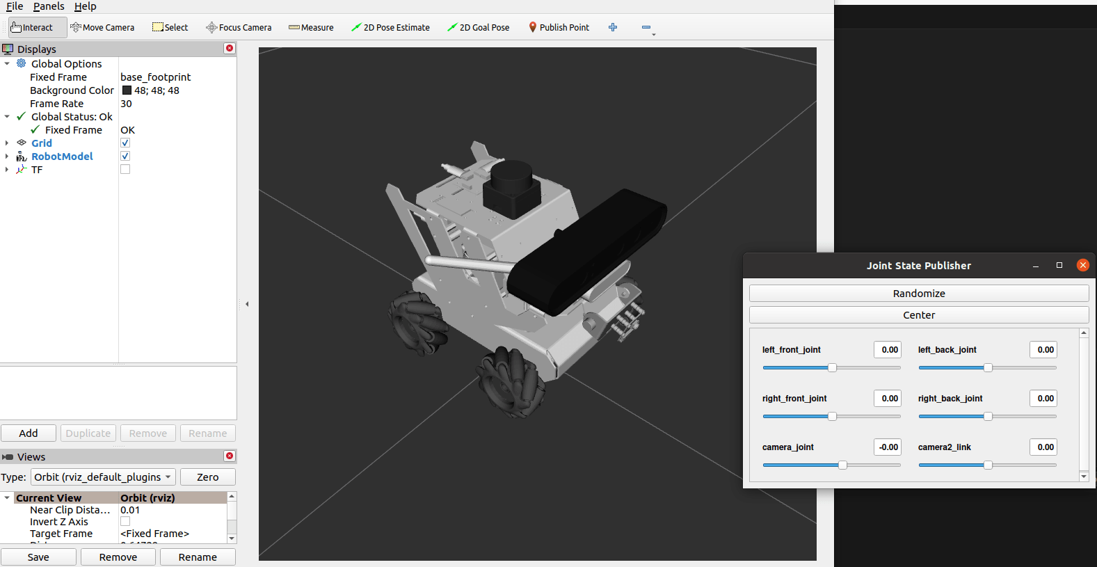
You can view TF tree, virtual machine terminal input,
xxxxxxxxxxros2 run tf2_tools view_frames.pyA frame.pdf file will be generated in the terminal directory, and then we can open it with the following command,
xxxxxxxxxxevince frames.pdf
7.4 Introduction to URDF
URDF, full name Unified Robot Description Format, translated into Chinese as Unified Robot description format, is a robot model file described in xml format, similar to D-H parameters.
xxxxxxxxxx <robot name="yahboomcar"></robot>The first xml mandatory field describes the version information of the xml.
The second line describes the current robot name; All information about the current robot is contained in the [Robot] TAB.
Components:
- link, the link, you can think of it as a human arm
- joint, think of it as a human elbow joint
link and joint relationship: Two links are connected by joints, imagine an arm with a lower arm (link) and a larger arm (link) connected by an elbow joint.
7.4.1. link
1) Introduction
In the URDF descriptive language, link is used to describe physical properties,
- Describes visual displays,
tags. - Describes collision properties,
tag. - Describes physical inertia. The
tag is not commonly used.
Links can also describe the link size, color, shape, inertial matrix, collision properties, each Link becomes a coordinate system.
2) Sample code (yahboomcar.urdf)
xxxxxxxxxx<link name="base_link"> <inertial> <origin xyz="0.00747327885898614 -0.000703137401396085 0.00844632750789007" rpy="0 0 0" /> <mass value="0.472828691870721" /> <inertia ixx="0.00023735992797554" ixy="1.96687462104139E-07" ixz="4.09403791310172E-05" iyy="0.000480258948998206" iyz="2.77544074265144E-07" izz="0.000585619745886075" /> </inertial> <visual> <origin xyz="0 0 0" rpy="0 0 0" /> <geometry> <mesh filename="package://yahboomcar_rviz/meshes/base_link.STL" /> </geometry> <material name=""> <color rgba="1 1 1 1" /> </material> </visual> <collision> <origin xyz="0 0 0" rpy="0 0 0" /> <geometry> <mesh filename="package://yahboomcar_rviz/meshes/base_link.STL" /> </geometry> </collision> </link>3) Label introduction
- origin
Describes pose information; The xyz attribute describes its coordinate position in the larger environment, and the rpy attribute describes its attitude.
- mess
It describes the quality of the link.
- inertia
The inertial reference frame, due to the symmetry of the rotational inertia matrix, requires only six upper triangular elements ixx, ixy, ixz, iyy, iyz, izz as properties.
- geometry
The label describes the shape; The main function of mesh properties is to load texture files, filename attribute texture path file address.
xxxxxxxxxx<box size="1 2 3"/> #box箱体,通过size属性描述盒装的长宽高。#box, using the size attribute to describe the length, width and height of the box.<cylinder length="1.6" radius="0.5"/> #cylinder圆状,通过`length`属性描述圆柱的高度,`radius`属性描述圆柱的的半径。#cylinder cylindrical, the height of the cylinder is described through the 'length' attribute, and the 'radius' attribute describes the radius of the cylinder.<sphere radius="1"/> #sphere球状,通过`radius`属性描述球的半径。#sphere The radius of the sphere is described by the 'radius' attribute.material
The label describes the material; The name attribute is mandatory field , can be empty, can be repeated. Red, green, blue, and transparency are described by the rgba attribute in the [color] tag, separated by a space. The color range is [0-1].
7.4.2. joints
1) Introduction
Describe the relationship between two joints, motion position and speed limits, kinematic and dynamic properties.
Joint type:
- fixed: fixed the joint. No movement allowed. It acts as a connection.
- continuous: rotates the joint. Can continue to rotate, there is no rotation Angle limit.
- revolute: Rotates the joint. Similar to continuous, there is a restriction on rotation Angle.
- prismatic: sliding joint. Move along an axis, with a position limitation.
- floating: Floating joints. Six degrees of freedom, 3T3R.
- planar: planar joint. Allow translations or rotations above plane orthogonality.
2) Sample code (yahboomcar.urdf)
xxxxxxxxxx<joint name="left_front_joint" type="continuous"> <origin xyz="0.06 0.08361 -0.03295" rpy="0 0 0" /> <parent link="base_link" /> <child link="left_front_wheel" /> <axis xyz="0 1 0" /> <limit lower="0" upper="0" effort="0" velocity="0" /> </joint>The name attribute in the [joint] tag is required , describes the name of the joint, and is unique. In the [joint]tag, the type attribute corresponds to six types of joints. 3) Label introduction
- origin
The child label refers to the relative position of the rotary joint in the coordinate system of the parent.
- parent, child
parent, child Indicates the two links to be connected. The parent is the reference, and the child rotates around the praent.
- axis
The child label indicates which axis (xyz) the child's corresponding link rotates around and the amount of rotation about the fixed axis.
- limit
child tags are primarily restricted to children. The lower and upper attributes limit the range of rotation radians, and the effort attribute limits the range of forces in the rotation process. The velocity property limits the speed of rotation in meters per second or m/s (plus or minus value, in cows or N).
- mimic
Describe the relationship between the joint and existing joints.
- safety_controller
Describes security controller parameters. Protect the movement of the robot joints.