yahboom
HomeLearn
Solution
Blog
Online Store
About Us
EN/中文
RDK X3 Robot📖
01. About RDK-X3-Robot
1. Instructions
  • 1. Introduction
  • 2. FAQ
  • 3. Battery and charger use precautions
  • 4.TF card expand capacity
2. Common problem analysis
02. Assembly video
  • Part1-Install Motor
  • Part2-Install Battert Fixing Column
  • Part3-Install Motor Coupling
  • Part4-Install Mecanum wheel
  • Part5-Install Expansion Board
  • Part6-Wiring Show
  • Part7-Install Main Control Board
  • Part8-Install Car Top Plate and Antenna
  • Part9-Install OLED Screen
  • Part10-Install Depth Camera(Optional)
  • Part11-Install OLED Screen
  • Part12-Install HD Camera
  • Part13-Install Top Plate
  • Part14-Install Right Side Plate
  • Part15-Motor Wiring Show
  • Part16-lnstall Car Body
  • Part17-Install Battery
  • Part18-Install Lidar
03. Remote control tutorial
  • 1. The phone APP remote tutorial
  • 2. USB wireless controller remote tutorial
04. ROS functional tutorial
  • 1. Introduction of extension board
  • 2. Set up STM32 development environment
  • 3. Key control buzzer sound
  • 4. FreeRTOS application
  • 5. Serial communication
  • 6. SBUS model remote control
  • 7. CAN bus communication
  • 8. RGB color light strip
  • 9. Timer interrupt control PWM servo
  • 10. Control serial steering gear
  • 11. Nine-axis attitude sensor to obtain data
  • 12. Control motor forward and reverse
  • 13. The timer captures encoder data
  • 14. Theory of robot kinematics analysis
  • 15. PID control robot motion
05. Basic control tutorial
  • 1. Update the firmware of the expansion module
  • 2. Install the Python driver library
  • 3. Set the type of bottom car
  • 4. Open and close the APP program control
  • 5. Turn hotspot mode on and off
  • 6. The buzzer blows
  • 7. Control the motor forward and reverse
  • 8. Control robot movement
  • 9. OLED display
  • 10. Control fan and lamp effect
06. Development environment setup
  • 1. Virtual Machine
  • 2. Linux Basics
  • 3. Remote connection
  • 4. Multi-computer communication configuration
  • 5. Bind the device ID
  • 6. Image installation and backup
07. ROS2 Basic Course
  • 1. Introduction to ROS2
  • 2. ROS2 install Humble
  • 3. ROS2 development environment
  • 4. ROS2 workspace
  • 5. ROS2 function package
  • 6. ROS2 node
  • 7. ROS2 topic communication
  • 8. ROS2 service communication
  • 9. ROS2 action communication
  • 10. ROS2 custom interface message
  • 11. ROS2 parameter service case
  • 12. ROS2 meta-function package
  • 13. ROS2 distributed communication
  • 14. ROS2 DDS
  • 15. ROS2 time related API
  • 16. ROS2 common command tools
  • 17. ROS2 rviz2 use
  • 18. ROS2 rqt toolbox
  • 19. ROS2 Launch startup file configuration
  • 20. ROS2 recording and playback tool
  • 21. ROS2 URDF model
  • 22. ROS2 Gazebo simulation platform
  • 23. ROS2 TF2 coordinate transformation
08. Robot chassis control
  • 1. PID algorithm theory
  • 2. Robot information release
  • 3. Robot control
  • 4. Robot state estimation
  • 5. Robot calibration
  • 6. Robot trajectory tracking
  • 7. URDF model
09. Lidar courses
  • 1. Introduction and use of lidar
  • 2. Lidar obstacle avoidance
  • 3. Lidar following
  • 4. Lidar guard
  • 5. Patrol
  • 6. gmapping algorithm
  • 7. cartographer algorithm
  • 8. Navigation and obstacle avoidance
  • 9. App mapping and navigation
10. OpenCV courses
  • 1. Introduction to OpenCV
  • 2. OpenCV geometric transformation
  • 3. OpenCV image processing
  • 4. OpenCV image beautification
  • 5. Qr code creation and identification
11. MIPI camera course
  • 1. Camera driver
  • 2. Adjust the color HSV value
  • 3. Color recognition
  • 4. Color tracking
  • 5. Color follow
  • 6. Qr code command
  • 7. Face detection
  • 8. Object detection
  • 9. Visual Inspection -OpenCV
  • 10. Visual inspection - Deep learning
  • 11. Human tracking
  • 12. Gesture control
12. Depth Camera courses
  • 1. Use depth camera
  • 2. Calibration of camera internal reference
  • 3. ROS+OpenCV Foundation
  • 4. AR vision
  • 5. Color tracking
  • 6. Object tracking
13. Multi vehicle control
  • 1. Multi-vehicle synchronous control
  • 2. Multi-vehicle navigation
Remote login control
  • 1. VNC and SSH remote login
  • 2. Jupyter lab login and case code running
Download
  • RemoteCtrl_APP(iOS/Android))
  • Mapping_APP(iOS_Android)
  • Code
  • System File
  • VM_File
  • Manual
  • Software_File
  • Hardware_File
  • ROS2_Basic_VM
Download ZIP

Welcome to RDK X3 Robot repository

6. Robot trajectory tracking

6. Robot trajectory tracking

6. Robot trajectory tracking6.1 Program function description6.2 Introduction to Principle6.3 Application Code Reference path6.4. Program Startup

6.1 Program function description

After the program runs, the car will follow the trajectory given in the.csv file. Starting rviz on the virtual machine side allows for visualization of trajectory tracking.

In addition, the [L1] button on the handle locks/turns on the car's motion controls. When motion control is enabled, the function is locked; This function can be turned on when the motion control is locked.

6.2 Introduction to Principle

PurePuesuit and MPC algorithms are commonly used control algorithms in automatic driving, aiming to smooth the trajectory points at the planning point and satisfy the kinematic trajectory of the vehicle itself.

Before talking about the implementation of the two algorithms in detail, it is necessary to understand that the two mainstream trajectory tracking algorithms are divided into geometric tracking and model-based tracking methods.

In this implementation, it can be basically regarded as known coordinate information, including (x,y,yaw) and curvature Kappa, and the steering Angle of the control quantity can be calculated, that is, the lateral amount of movement, so that the car can run smoothly in the track.

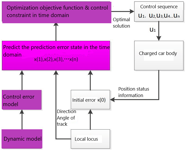
Take the MPC as an example, as shown below:
 

1684835327956

PurePursuit

The pure tracking algorithm puts forward the concept of "pre-sight distance", and finds the qualified target waypoint in the target trajectory according to the pre-sight distance. The judgment logic is to find which point on the target trajectory and the relative distance between the current vehicle position is equal to the pre-sight distance, then the point is the target point at the current moment. The control target is to calculate how much front wheel deflection Angle can make the current car position move to the target position. On this basis, may wish to briefly look at the core point, what is the pre-sight distance.

In simple terms, the pre-sight distance is like finding a tracking reference point when driving, for example, when driving on a straight road, we will choose a higher speed, and we are used to considering the point far ahead as a tracking reference point; When driving on a curve, it will choose to slow down, and it is customary to choose a closer point as a tracking reference point. So this value is a value that we can set ourselves. The setting of this value will also greatly affect the movement of the car. For example, in the findCloestindex function in this example, we find the nearest point based on the preview distance:

xxxxxxxxxx
//公式 : ld=l+kvld=l+kv (过于依赖前视距离的选取,可以采用动态前视距离ld=l+kvld=l+kv其中l、kl、k为系数,根据速度调整前视距离)
// Formula: ld=l+kvld=l+kv (too dependent on the selection of forward looking distance, can use dynamic forward looking distance ld=l+kvld=l+kv, where l, kl, k are the coefficients, adjust the forward looking distance according to the speed)
double ld = kv*linear_x+ld0;
double ld_now = 0;
while(ld_now<ld && index<=(int)xr.size()) {
    double dx_ref = xr[index+1] - xr[index];
    double dy_ref = yr[index+1] - yr[index];
    ld_now += sqrt(pow(dx_ref,2)+pow(dy_ref,2));
    index++;
}

After obtaining this point, calculate the Angle according to the model limitations of the car itself:

xxxxxxxxxx
double PurePursuit::calSteeringAngle(double alpha,double ld) 
{
    double steer = atan2(2*track*sin(alpha),ld);
    if (steer > M_PI) {
        steer -= M_PI*2;
        } else if (steer < (-M_PI)) {
        steer += M_PI*2;
        }
    return steer;
}

MPC

The MPC is more complex to solve. Show the code frame directly:

  1. Obtain car body parameters.
  2. Select state quantity and control quantity.
  3. The AB matrix is discretized, and the perturbation matrix is added to Apollo.
  4. Set the QR matrix.
  5. Set the number of predicted steps and augment the ABQR.
  6. Set the constraints of relevant parameters and obtain the values of each sensor.
  7. Solve the control quantity u, and finally get u[0].

For more specific logic, see this link:https://blog.csdn.net/u013914471/article/details/83824490

6.3 Application Code Reference path

After SSH connection car, the location of the function source code is located at,

xxxxxxxxxx
#Purepursuit
/userdata/yahboomcar_ws/src/yahboomcar_autonomous/Purepursuit/src/purepursuit.cc
#MPC
/userdata/yahboomcar_ws/src/yahboomcar_autonomous/MPC/launch/yahboomcar_mpc.launch.py

Where the trace's.csv file is located,

xxxxxxxxxx
/userdata/yahboomcar_ws/src/yahboomcar_autonomous/waypoints/path.csv

6.4. Program Startup

After SSH connects to the car, terminal input,

xxxxxxxxxx
#启动底盘# Start chassis
ros2 launch yahboomcar_bringup yahboomcar_bringup_launch.py
#Purepursuit
ros2 run yahboomcar_autonomous purepursuit_node
#MPC
ros2 launch yahboomcar_autonomous yahboomcar_mpc.launch.py

Enter on the VM.

xxxxxxxxxx
rviz2


Robot calibration
URDF model

COMPANY

  • About us
  • Team Style
  • Blog

LEARNING & EXPLORATION

  • Tutorials
  • Edge AI hardware
  • Educational robots
  • Embedded intelligent hardware

WHERE TO BUY

  • Yahboom Online Store
  • Amazon
  • Alibaba
  • AliExpress
  • Mercado

TECHNOLOGY SUPPORT

  • Email: support@yahboom.com

BE A DISTRIBUTOR

  • Email: sales@yahboom.com
QR Code

Copyright © 2017-2026 Yahboom. All Rights Reserved.

EN/中文