Welcome to RDK X3 Robot repository
2. OpenCV geometric transformation
2. OpenCV geometric transformation
2. OpenCV geometric transformation2.1. Image scaling2.2. Image cropping2.3. Image translation2.4.Image mirroring
Before running the sample program, you need to switch to the directory where the code is located. SSH connects the car, runs at the terminal,
xxxxxxxxxxcd /userdata/yahboomcar_ws/src/yahboomcar_astra/opencv_examples2.1. Image scaling
After the car terminal switches to the directory where the code is located, run the program,
xxxxxxxxxxpython3 2_1.py
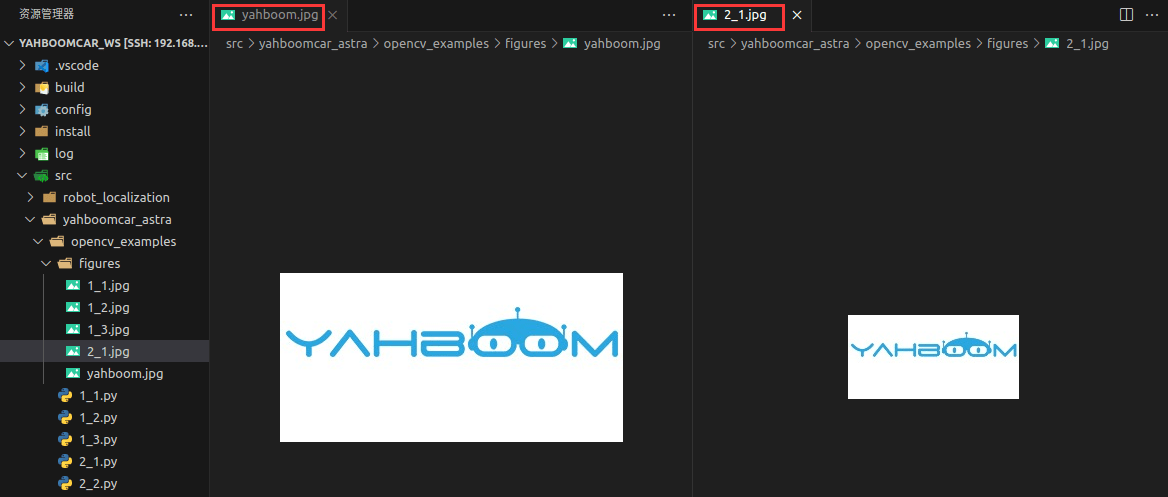
xxxxxxxxxximport cv2if __name__ == '__main__': img = cv2.imread('figures/yahboom.jpg') print(img.shape) x, y = img.shape[0:2] img_resize = cv2.resize(img, (int(y / 2), int(x / 2))) cv2.imwrite('figures/2_1.jpg', img_resize) print(img_resize.shape)'''图像缩放:cv2.resize(InputArray src,OutputArray dst,Size,fx,fy,interpolation) InputArray src:输入图片 OutputArray ds:输出图片 Size:输出图片尺寸 fx,fy:沿x轴,y轴的缩放系数 interpolation:插入方式,有以下选择, INTER_NEAREST(最近邻插值) INTER_LINEAR(双线性插值,默认设置) INTER_AREA(使用像素区域关系进行重采样) INTER_CUBIC(4x4像素邻域的双三次插值) INTER_LANCZOS4(8x8像素邻域的Lanczos插值)Zoom: cv2. Resize (InputArray SRC, OutputArray DST, Size, fx, fy, interpolation) InputArray src: Input the image OutputArray ds: Output the image Size: size of the output image fx,fy: Scale factor along the X-axis, Y-axis interpolation: Interpolation, available from the following, INTER_NEAREST INTER_LINEAR (default) INTER_AREA (resampling using pixel area relationships) INTER_CUBIC (bicubic interpolation in 4x4 pixel neighborhood) INTER_LANCZOS4 (Lanczos interpolation for 8x8 pixel neighborhood)'''Terminal output the size of the original image and the reduced image (representing the width, height and number of channels of the image, respectively),

Open the image and you can see the difference in size,
2.2. Image cropping
After the car terminal switches to the directory where the code is located, run the program,
xxxxxxxxxxpython3 2_2.py
xxxxxxxxxximport cv2if __name__ == '__main__': img = cv2.imread('figures/yahboom.jpg') dst = img[0:100,100:200] # 选取区域X:0-100 Y:100-200,不能超过原图像分辨率 # Select the region X: 0-100 Y: 100-200, can not exceed the original image resolution cv2.imwrite('figures/2_2.jpg', dst)The resulting image is shown here,

2.3. Image translation
After the car terminal switches to the directory where the code is located, run the program,
xxxxxxxxxxpython3 2_3.py
xxxxxxxxxximport cv2import numpy as npif __name__ == '__main__': img = cv2.imread('figures/yahboom.jpg') imgInfo = img.shape height = imgInfo[0] width = imgInfo[1] matShift = np.float32([[1,0,100],[0,1,50]]) # 2*3 dst = cv2.warpAffine(img, matShift, (width,height)) cv2.imwrite('figures/2_3.jpg', dst)'''图像平移:cv2.warpAffine(src,M,dsize[,dst[,flags[,borderMode[,borderValue]]]]) src:输入图像 M:仿射变换矩阵,一般反映平移或旋转的关系(InputArray类型) dsize:输出图像的大小 flags:插值方法的组合(int类型) borderMode:边界像素模式(int类型) borderValue:(重点!)边界填充值; 默认情况下,它为0一般只设置前三个参数就可以实现基本的仿射变换效果。Image translation:cv2.warpAffine(src,M,dsize[,dst[,flags[,borderMode[,borderValue]]]]) src: Input the image M: Affine transformation matrix, generally reflecting translation or rotation relations (InputArray type) dsize: indicates the size of the output image flags: Combination of interpolation methods (int type) borderMode: Border pixel mode (int type) borderValue: (Point!) Boundary filling value; By default, it is 0,Generally, only the first three parameters can be set to achieve the basic affine transformation effect.'''The resulting image is shown here,
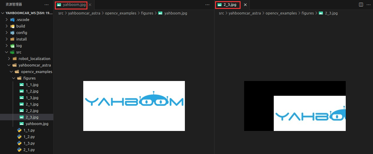
How to get the transformation matrix M? Here is an example,
Convert the original image src to the target image dst through the transformation matrix M:
dst(x, y) = src(M11x + M12y+M13, M21x+M22y+M23)
Move the original image src by 100 to the right and 50 pixels down, and the corresponding relationship is as follows:
dst(x, y) = src(x+100, y+50)
To complete the above expression, namely:
dst(x, y) = src(1·x + 0·y + 100, 0·x + 1·y + 50)
According to the above expression, it can be determined that the values of each element in the corresponding transformation matrix M are:
M11=1, M12=0, M13=100, M21=0, M22=1, M23=50.
Substituting the above values into the transformation matrix M, we get:
M = [[1,0,100],[0,1,50]
2.4.Image mirroring
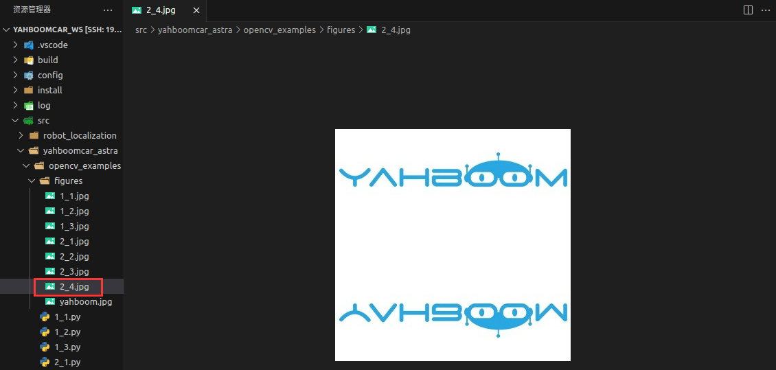
There are two kinds of image image transformation: horizontal image and vertical image. The horizontal mirror takes the vertical center line of the image as the axis, and swaps the pixels of the image, that is, switches the left half of the image and the right half of the image. Vertical mirroring is based on the horizontal center line of the image as the axis, the upper part of the image and the lower part of the image.
Transformation principle:
Set the width of the image to width and the length to height. (x,y) is the coordinate after transformation, (x0,y0) is the coordinate of the original image,
- Horizontal mirror transform
Forward mapping: x=width-x0-1,y=y0
Backward mapping: x0=width-x-1,y0=y
- Vertical mirror transform
Map up: x=x0,y=height-y0-1
Downward mapping: x0=x, y0=height-y-1
Summary: In the horizontal image transformation, the entire image is traversed, and then each pixel is processed according to the mapping relationship. In fact, the horizontal mirror transformation is to change the column of the image coordinate to the right, and the right column to the left, which can be transformed in column units. The same is true of the vertical mirror image transformation, which can be transformed in units of behavior.
The following takes vertical transformation as an example, after the car terminal switches to the directory where the code is located, run the program,
xxxxxxxxxxpython3 2_4.py
xxxxxxxxxximport cv2import numpy as npif __name__ == '__main__': img = cv2.imread('figures/yahboom.jpg') imgInfo = img.shape height = imgInfo[0] width = imgInfo[1] deep = imgInfo[2] newImgInfo = (height*2,width,deep) dst = np.zeros(newImgInfo,np.uint8)#uint8 for i in range(0,height): for j in range(0,width): dst[i,j] = img[i,j] dst[height*2-i-1,j] = img[i,j] cv2.imwrite('figures/2_4.jpg', dst)The resulting image is shown here,