yahboom
HomeLearn
Solution
Blog
Online Store
About Us
EN/中文
RDK X3 Robot📖
01. About RDK-X3-Robot
1. Instructions
  • 1. Introduction
  • 2. FAQ
  • 3. Battery and charger use precautions
  • 4.TF card expand capacity
2. Common problem analysis
02. Assembly video
  • Part1-Install Motor
  • Part2-Install Battert Fixing Column
  • Part3-Install Motor Coupling
  • Part4-Install Mecanum wheel
  • Part5-Install Expansion Board
  • Part6-Wiring Show
  • Part7-Install Main Control Board
  • Part8-Install Car Top Plate and Antenna
  • Part9-Install OLED Screen
  • Part10-Install Depth Camera(Optional)
  • Part11-Install OLED Screen
  • Part12-Install HD Camera
  • Part13-Install Top Plate
  • Part14-Install Right Side Plate
  • Part15-Motor Wiring Show
  • Part16-lnstall Car Body
  • Part17-Install Battery
  • Part18-Install Lidar
03. Remote control tutorial
  • 1. The phone APP remote tutorial
  • 2. USB wireless controller remote tutorial
04. ROS functional tutorial
  • 1. Introduction of extension board
  • 2. Set up STM32 development environment
  • 3. Key control buzzer sound
  • 4. FreeRTOS application
  • 5. Serial communication
  • 6. SBUS model remote control
  • 7. CAN bus communication
  • 8. RGB color light strip
  • 9. Timer interrupt control PWM servo
  • 10. Control serial steering gear
  • 11. Nine-axis attitude sensor to obtain data
  • 12. Control motor forward and reverse
  • 13. The timer captures encoder data
  • 14. Theory of robot kinematics analysis
  • 15. PID control robot motion
05. Basic control tutorial
  • 1. Update the firmware of the expansion module
  • 2. Install the Python driver library
  • 3. Set the type of bottom car
  • 4. Open and close the APP program control
  • 5. Turn hotspot mode on and off
  • 6. The buzzer blows
  • 7. Control the motor forward and reverse
  • 8. Control robot movement
  • 9. OLED display
  • 10. Control fan and lamp effect
06. Development environment setup
  • 1. Virtual Machine
  • 2. Linux Basics
  • 3. Remote connection
  • 4. Multi-computer communication configuration
  • 5. Bind the device ID
  • 6. Image installation and backup
07. ROS2 Basic Course
  • 1. Introduction to ROS2
  • 2. ROS2 install Humble
  • 3. ROS2 development environment
  • 4. ROS2 workspace
  • 5. ROS2 function package
  • 6. ROS2 node
  • 7. ROS2 topic communication
  • 8. ROS2 service communication
  • 9. ROS2 action communication
  • 10. ROS2 custom interface message
  • 11. ROS2 parameter service case
  • 12. ROS2 meta-function package
  • 13. ROS2 distributed communication
  • 14. ROS2 DDS
  • 15. ROS2 time related API
  • 16. ROS2 common command tools
  • 17. ROS2 rviz2 use
  • 18. ROS2 rqt toolbox
  • 19. ROS2 Launch startup file configuration
  • 20. ROS2 recording and playback tool
  • 21. ROS2 URDF model
  • 22. ROS2 Gazebo simulation platform
  • 23. ROS2 TF2 coordinate transformation
08. Robot chassis control
  • 1. PID algorithm theory
  • 2. Robot information release
  • 3. Robot control
  • 4. Robot state estimation
  • 5. Robot calibration
  • 6. Robot trajectory tracking
  • 7. URDF model
09. Lidar courses
  • 1. Introduction and use of lidar
  • 2. Lidar obstacle avoidance
  • 3. Lidar following
  • 4. Lidar guard
  • 5. Patrol
  • 6. gmapping algorithm
  • 7. cartographer algorithm
  • 8. Navigation and obstacle avoidance
  • 9. App mapping and navigation
10. OpenCV courses
  • 1. Introduction to OpenCV
  • 2. OpenCV geometric transformation
  • 3. OpenCV image processing
  • 4. OpenCV image beautification
  • 5. Qr code creation and identification
11. MIPI camera course
  • 1. Camera driver
  • 2. Adjust the color HSV value
  • 3. Color recognition
  • 4. Color tracking
  • 5. Color follow
  • 6. Qr code command
  • 7. Face detection
  • 8. Object detection
  • 9. Visual Inspection -OpenCV
  • 10. Visual inspection - Deep learning
  • 11. Human tracking
  • 12. Gesture control
12. Depth Camera courses
  • 1. Use depth camera
  • 2. Calibration of camera internal reference
  • 3. ROS+OpenCV Foundation
  • 4. AR vision
  • 5. Color tracking
  • 6. Object tracking
13. Multi vehicle control
  • 1. Multi-vehicle synchronous control
  • 2. Multi-vehicle navigation
Remote login control
  • 1. VNC and SSH remote login
  • 2. Jupyter lab login and case code running
Download
  • RemoteCtrl_APP(iOS/Android))
  • Mapping_APP(iOS_Android)
  • Code
  • System File
  • VM_File
  • Manual
  • Software_File
  • Hardware_File
  • ROS2_Basic_VM
Download ZIP

Welcome to RDK X3 Robot repository

15. PID control robot motion

15. PID controls robot motion

15. PID controls robot motion15.1. Experimental purpose15.2. Configure pin information15.3. Analysis of experimental flow chart15.4. Core code interpretation15.5. Hardware connection15.6. Experimental effect

15.1. Experimental purpose

The robot motion is controlled and the running speed of the robot is controlled by PID algorithm.

Because different models require different drive codes, here only the McNamum wheel car as an example for demonstration.

15.2. Configure pin information

  1. Import ioc file from Encoder project and name it Car_Motion.

There is no need to add additional content, and the final chip configuration pin is shown as follows:
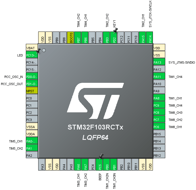
image-20220311171929134

15.3. Analysis of experimental flow chart
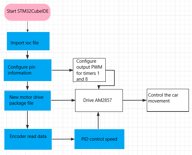
image-20220325113943274

15.4. Core code interpretation

  1. Create bsp_pid.h and bsp_pid.c, and add the following information to bsp_pid.h:
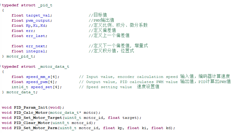
image-20220311182153477

  1. Create the following content in the bsp_pid.c file:

Initialize PID parameters:
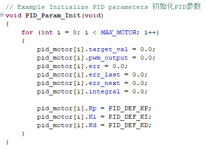
image-20220311182232217

  1. Calculation formula of incremental PID.
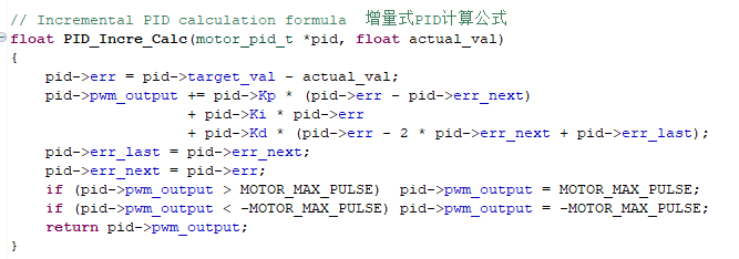
image-20220311182312127

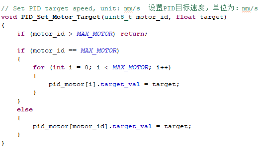
  1. Set the target value.

image-20220311182400564

  1. Obtain PWM output value through PID calculation.
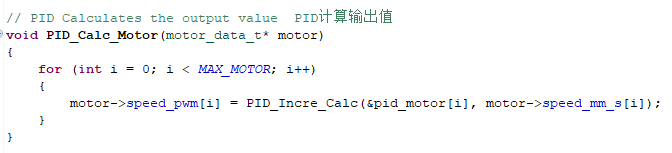
image-20220311182458461

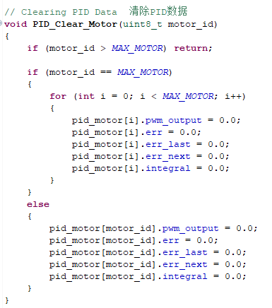
  1. Clear PID parameters.

image-20220311182542931

  1. Create bsp_motion.h and bsp_motion.c files.
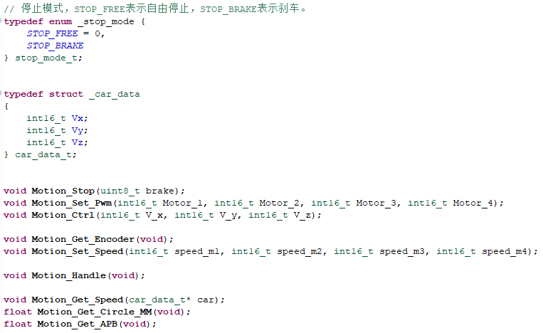
image-20220311183152424

  1. Obtain and calculate the speed of the car from the encoder.
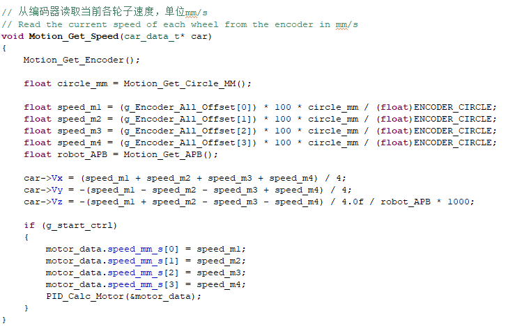
image-20220325115058394

  1. According to the speed value, the PWM data of the motor is updated again, so as to achieve the role of speed regulation.
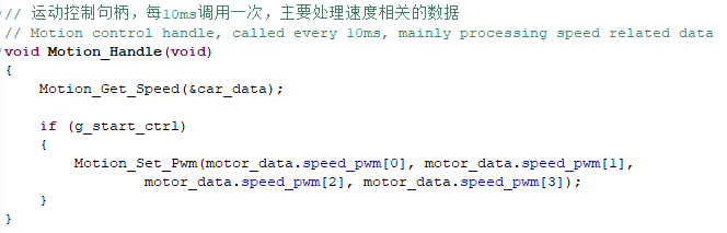
image-20220325115219282

15.5. Hardware connection

The motor connection line needs to be connected to the corresponding motor as shown in the figure below, otherwise it may cause the problem that the program does not match the phenomenon. Motor 1 corresponds to the Motor in the upper left corner of the body, Motor 2 corresponds to the Motor in the lower left corner, motor 3 corresponds to the motor in the upper right corner, and Motor 4 corresponds to the motor in the lower right corner.
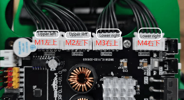
image-20220311143208773

Because the power of the motor is relatively large, do not directly use USB 5V power supply for the expansion board, and must use battery power supply.

15.6. Experimental effect

Since the motor will turn when started, please set up the car before the experiment, and the motor wheels are suspended to avoid rampaging.

After burning the program, the LED light flashes every 200 milliseconds. Press KEY1 to make the car move forward, and press KEY1 again to stop the car.


Theory of robot kinematics analysis
Update the firmware of the expansion module

COMPANY

  • About us
  • Team Style
  • Blog

LEARNING & EXPLORATION

  • Tutorials
  • Edge AI hardware
  • Educational robots
  • Embedded intelligent hardware

WHERE TO BUY

  • Yahboom Online Store
  • Amazon
  • Alibaba
  • AliExpress
  • Mercado

TECHNOLOGY SUPPORT

  • Email: support@yahboom.com

BE A DISTRIBUTOR

  • Email: sales@yahboom.com
QR Code

Copyright © 2017-2026 Yahboom. All Rights Reserved.

EN/中文